Hardware Installation
MC24 system has the following positions of mounting holes:
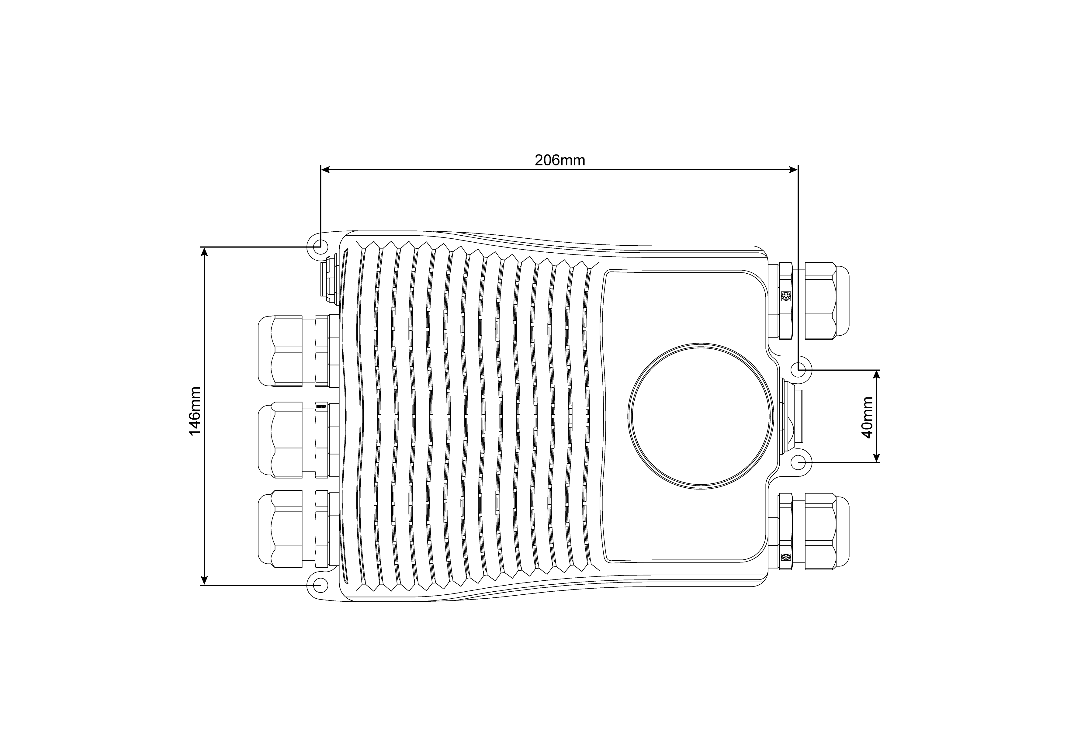
Mounting Holes
Pinout
The user connector pinout is shown in the following figures and table:
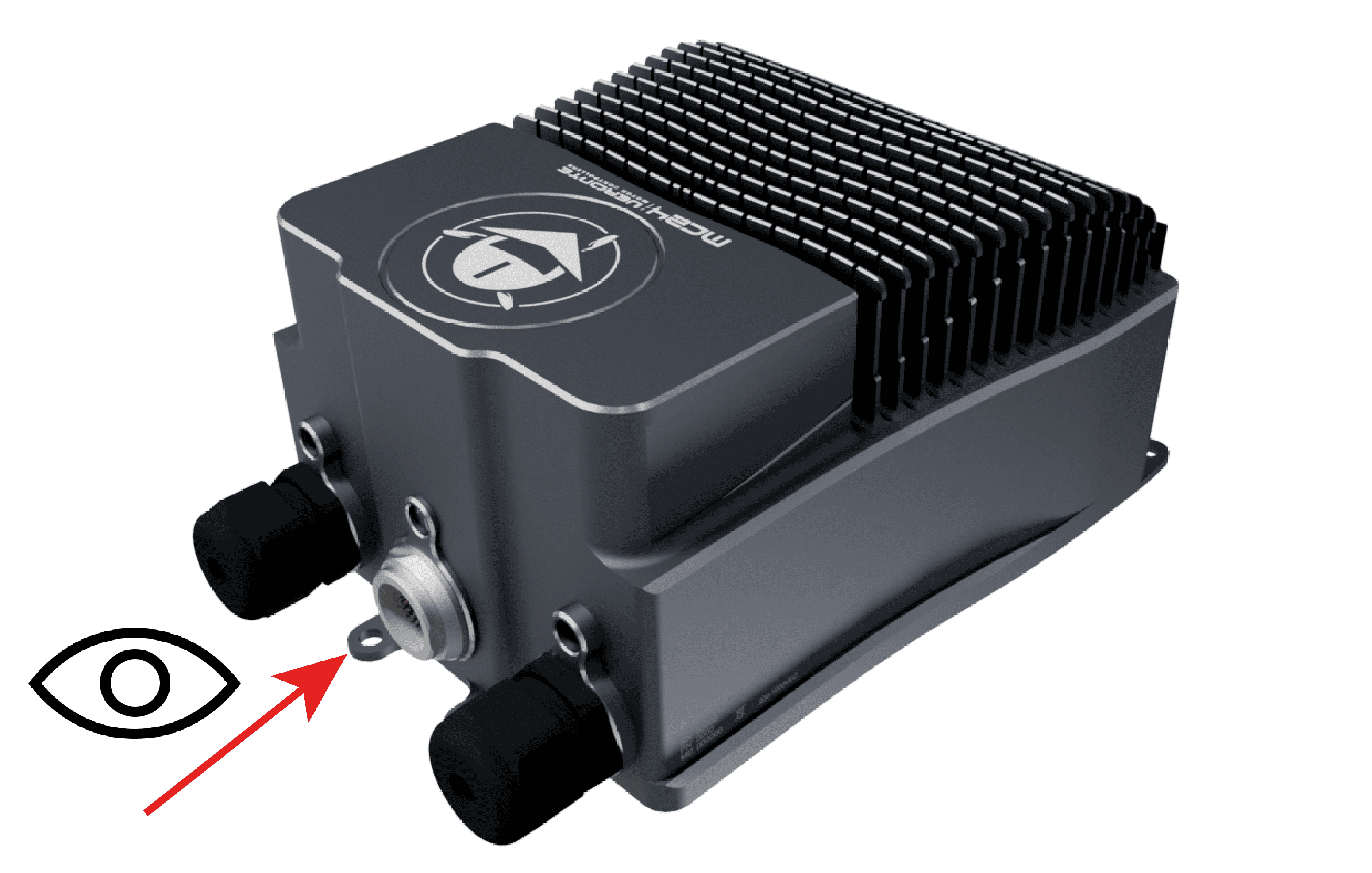
Point of view
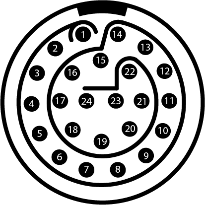
Pin numbers of user connector
PIN |
Signal |
Type |
Description |
|---|---|---|---|
1 |
ERROR_SIGNAL |
Digital Status Signal |
High: OK, Low: NO OK |
2 |
OPTO_PWM |
Optocoupled Digital Input |
|
3 |
VCC |
Digital Supply |
8-20 V |
4 |
GND |
Digital Ground |
|
5 |
CANA_P |
CAN Communications |
|
6 |
CANA_N |
CAN Communications |
|
7 |
CANB_N |
CAN Communications |
|
8 |
GND |
Digital Ground |
|
9 |
RS485_OUT_P |
RS-485 Communication |
|
10 |
RS485_OUT_N |
RS-485 Communication |
|
11 |
FAN_PWM |
Digital Output |
|
12 |
GND |
Digital Ground |
|
13 |
RS485_IN_P |
RS-485 Communication |
|
14 |
RS485_IN_N |
RS-485 Communication |
|
15 |
RS485_GND |
RS-485 Communication |
|
16 |
OPTO_RETURN |
Optocoupled Return |
|
17 |
GND |
Digital Ground |
|
18 |
CANB_P |
CAN Communications |
|
19 |
USB_N |
USB Communication |
|
20 |
RS232_RX |
RS-232 Communication |
|
21 |
GND |
Digital Ground |
|
22 |
RS232_TX |
RS-232 Communication |
|
23 |
USB_P |
USB Communication |
|
24 |
CAN_GND |
CAN Ground |
The sensors connector pinout is shown in the following figures and table:
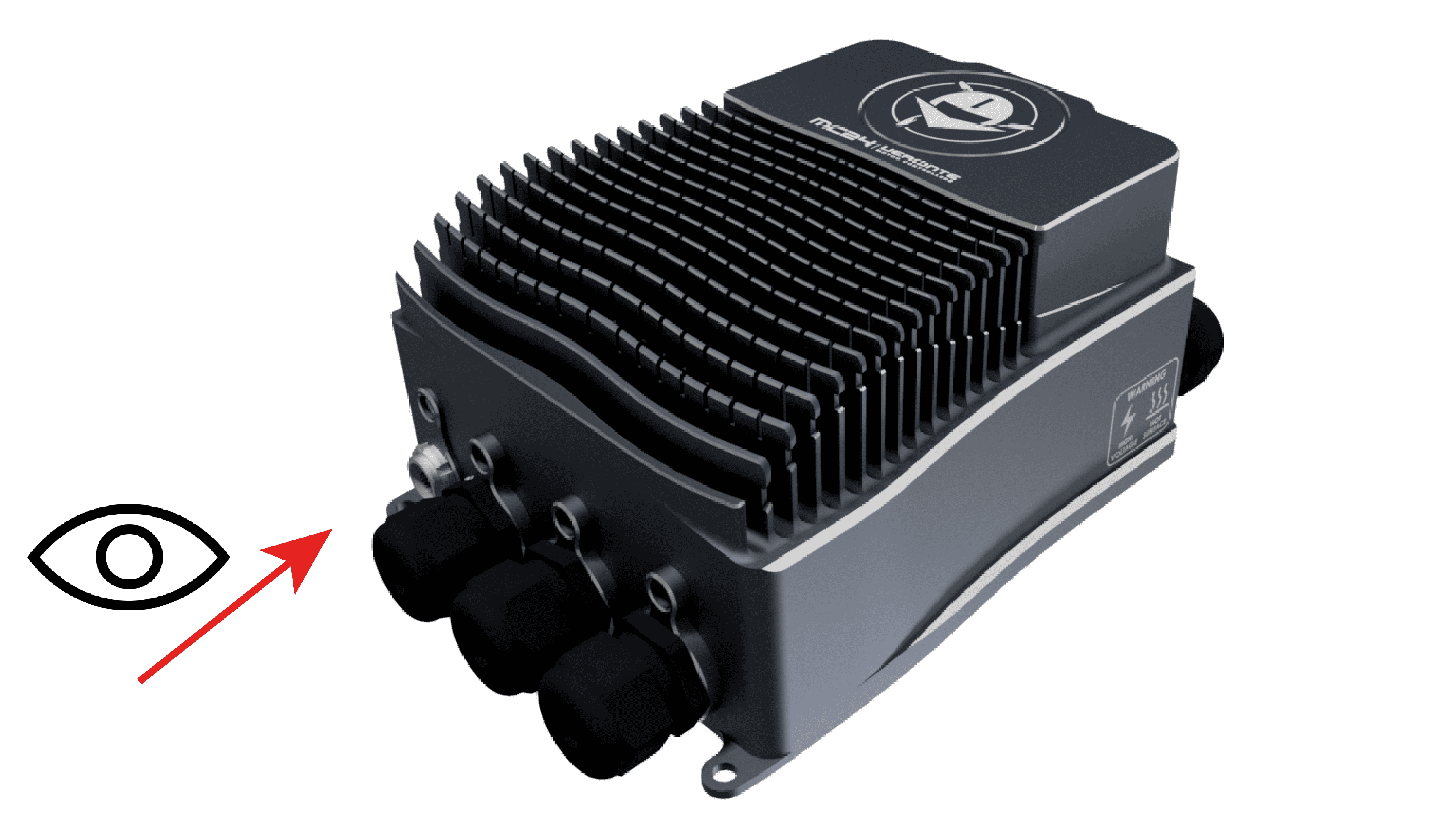
Point of view
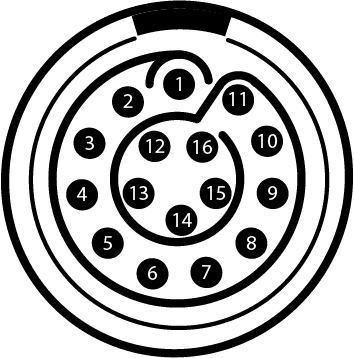
Pin numbers of sensor connector
PIN |
Signal |
Type |
Description |
|---|---|---|---|
1 |
HALL_1 |
Hall Sensor 1 Input |
|
2 |
NC |
No Connect |
|
3 |
NC |
No Connect |
|
4 |
NC |
No Connect |
|
5 |
COS_SIGNAL |
Cosine Input |
SIN/COS Encoder |
6 |
SIN_SIGNAL |
Sine Input |
SIN/COS Encoder |
7 |
ISO_GND |
Isolated Ground |
|
8 |
NTC/PTC |
NTC/PTC Input |
|
9 |
ISO_GND |
Isolated Ground |
|
10 |
HALL_3 |
Hall Sensor 3 Input |
|
11 |
HALL_2 |
Hall Sensor 2 Input |
|
12 |
ISO_GND |
Isolated Ground |
|
13 |
ISO_GND |
Isolated Ground |
|
14 |
5V |
Isolated 5 V |
|
15 |
VOLTAGE_REF |
Voltage Reference Output |
Use for NTC |
16 |
ISO_GND |
Isolated Ground |
ESC-Motor Wiring
The polarity and connection is indicated in the following image.
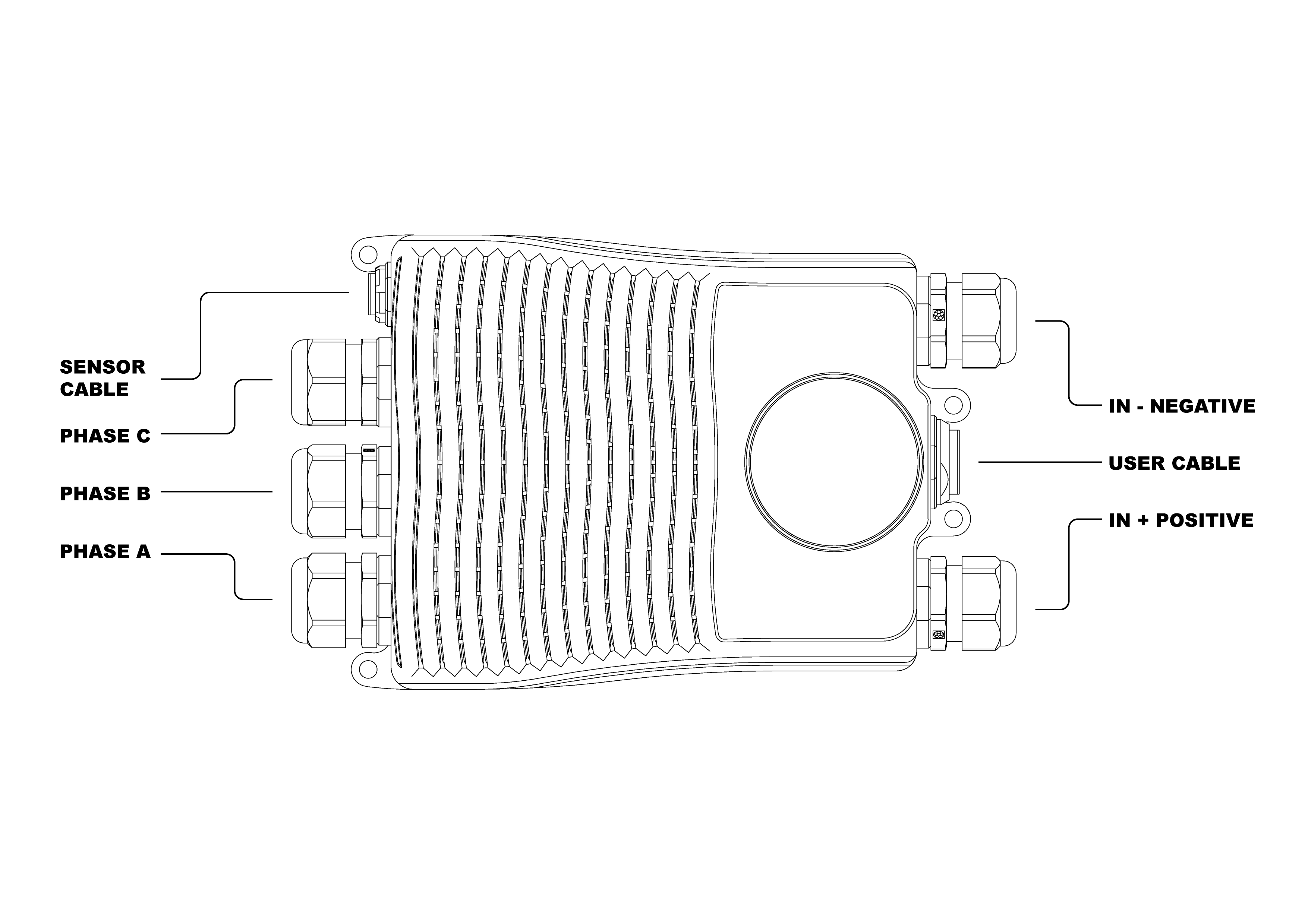
The section of the cables must be dimensioned according to input/output max power
Note
The polarity connection of the input must be respected, otherwise a short circuit may occour. Connection of the phases can be done freely, however, it will affect the direction of rotation of the motor.