 Input/Output
I/O Setup
In this panel the user can establish the relationship between a determined signal with a I/O port and the duties they are performing. This allows users to configure external sensors, custom messages, etc.
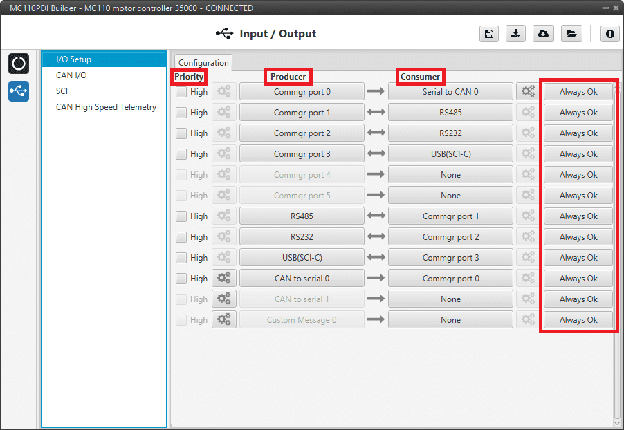
I/O Setup panel
Priority: Connections between I/O ports can be marked with high priority with this checkbox. If enabled, they will run at high frequency: 1000 Hz.
Producer: Functions for creating and sending messages.
Consumer: Functions for receiving and parsing messages.
Bit: This assigns each connection a bit in a way that allows this connection to be activated/deactivated depending on the status of the selected bit.
By default, the ‘Always Ok’ bit is set to all connections so that they are always active.
Firstly, user has to configure the Producer selecting the I/O port or information to use. Later, user has to configure the Consumer by clicking on an element, a new window will be displayed to select an item. The relationship between them can be unidirectional (Bind \(\rightarrow\)) or bidirectional (Bind Bidirectional \(\leftrightarrow\)), the last enables a port to receive or send information.
The following I/O ports are available:
Field |
Description |
|---|---|
RS232 |
Serial Port 232 (SCI-B) |
RS485 |
Serial Port 485 (SCI-A) |
USB (SCI-C) |
USB Port |
Commgr port |
COM Manager ports send and receive VCP messages. This is the protocol used by Veronte products to communicate. For more information on VCP, read the VCP user manual |
Custom Message producer |
This allows user to send a serial custom message, see Serial custom messages section |
CAN to serial / Serial to CAN |
Serial to CAN sends serial streams over a CAN Bus / CAN to serial undoes the transformation ‘Serial to CAN’ |
More information about some elements can be found in the following sections.
Serial Custom Messages
Warning
MC110 has a serial limitation of 64 vectors (fieldset).
In addition, there is a limit shared with CAN Custom Messages:
Maximum number of vectors (fieldset): 104
Maximum number of fields: 2000
It is possible to configure the messages sent through the serial port and its conversion to system variables by selecting the option Custom Message and configuring the I/O port.
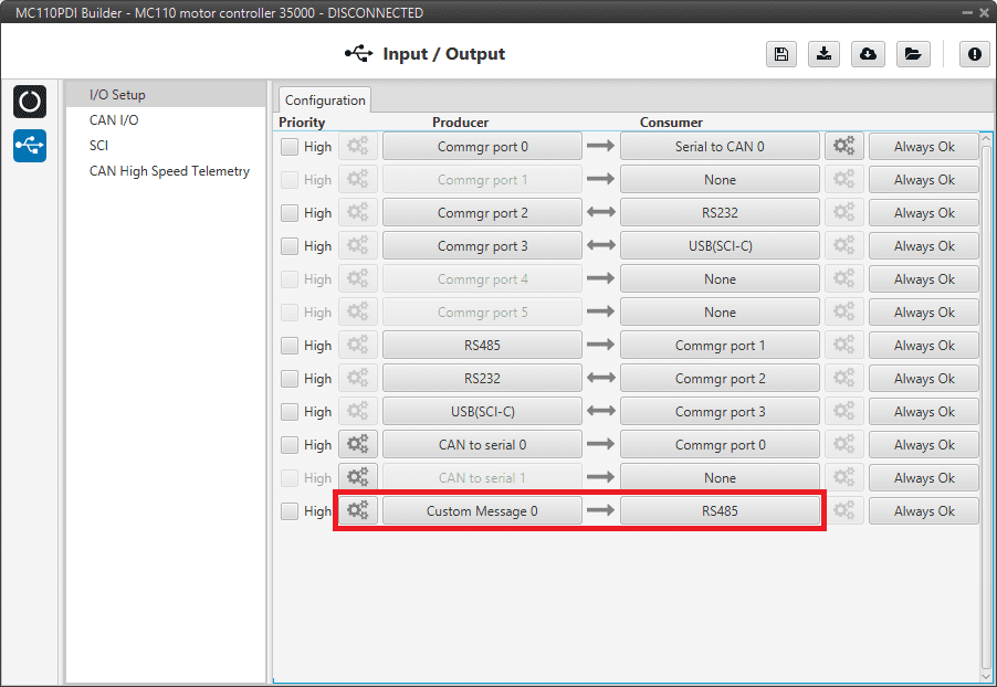
Serial Custom Message
To configure a serial custom message, the user must follow the next steps:
Press the configuration button (
 icon) and a pop-up window will be displayed.
In this window press the
 icon to add a custom message, the user can choose between System variables, ADSB Vehicle or External Sensor.
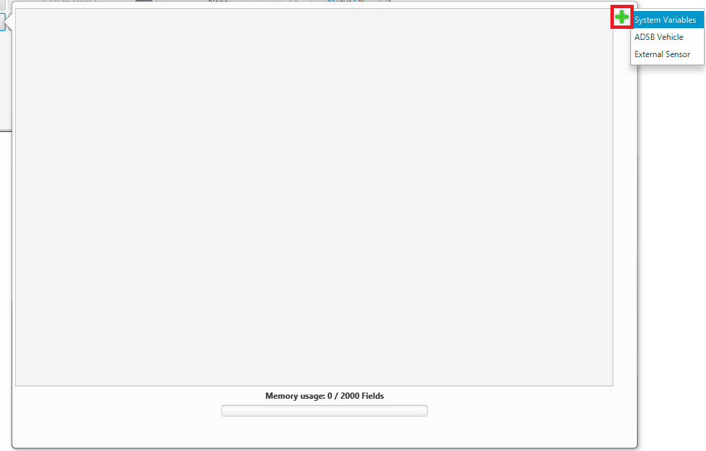
Serial Custom Message configuration
Note
The difference between choosing System Variables, ADSB Vehicle or External Sensor is that when the user selects Variable as the custom message type, only system variables will appear when System Variables is selected, only ADSB variables when ADSB Vehicle is selected and only variables related to external sensors if External Sensor is selected.
When it is already added, the following options are available to configure a custom message:

Producer Serial Custom Message configuration
Endianness: Depending on the order in which the device outputs the message, it is possible to select:
Big endian: Set the value from left to right.
Little endian: Set the value from right to left.
Mixed endian: Some devices use this format. If users need to configure it, please contact the support team (create a ticket in the customer’s Joint Collaboration Framework; for more information, see Tickets section of the JCF manual).
Period: It is the inverse of the send frequency.
Delay: It is a delay applied before sending the message. This serves to send messages with the same period without overloading the serial bus.
To create the structure of the message, click on the edit message button (
 icon) and then press the icon to add fields to it.
The following type of messages are available to configure a structure: Variable, Checksum, Matcher, Skip and Parse ASCII.
The configuration of each structure is covered in Custom Messages types - Input/Output section of the 1x PDI Builder user manual.
Warning
Before configuring any message, user has to know the structure it has to have according to the device that is connected to the port. Each device may have a different message structure when it sends or receives information.
CAN I/O
A CAN (Controller Area Network) Bus is a robust standard communication protocol for vehicles widely used in the aviation sector. MC110 has two CAN buses that can be configured independently.
The structure of a CAN message can be seen in the following image:

CAN message structure
Only the ID is introduced in the system, the rest of the message layout is already coded. The data field is built by the user to send, and parsed when received.
The baud rate of both CAN buses can be configured in the Mailboxes panel.
Configuration
This menu allows the configuration of the CAN inputs and outputs.
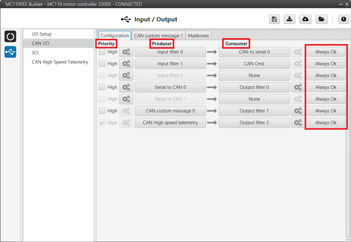
CAN configuration panel
In this menu, the user can find the same ‘columns’ (Priority, Producer, Consumer and Bit) as in the I/O Setup panel.
Warning
In CAN, in Low state the specified period is not guaranteed but in High state it is.
However, only those messages that are critical for external devices should be set as high priority, as this may disrupt the proper functioning of Veronte MC110.
MC110 has the following list of producers:
Input Filter: Those CAN messages received in one filter can no longer be received in subsequent filters.
The following parameters need to be configured by clicking on
: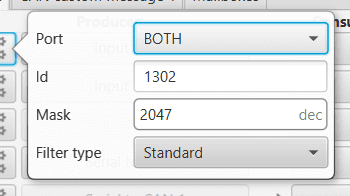
Input Filter configuration
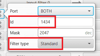
Port: It is required to configure the CAN bus from which it listens, the user can choose between CAN A, CAN B or BOTH.
Id: CAN Id must be set and it is used to identify messages. The value set has to be decimal format.
Mask: A CAN Id mask can be set to filter messages. The mask defines the bits that should match.
For example, to admit standard Ids (11 bits) from 8 to 11 (100 to 111 in binary) the user should set the mask to binary 11111111100, that is 2044 in decimal.
Warning
Make sure that mask is set properly to be able to receive the desired CAN messages.
Filter type: The available options are Standard (frame format with a 11-bit identifier), Extended (frame format with a 29-bit identifier) and Both.
Serial to CAN: Serial messages through CAN output, it has to be connected to I/O Setup consumer. It can be configured in
, a pop-up window will appear:Warning
For correct communication, mark it as High priority (with the Priority checkbox).
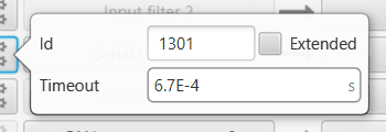
Serial to CAN configuration
Id: CAN Id must be set and it is used to identify messages. The value set has to be decimal format.
Extended: If it is enabled, the frame format will be ‘Extended’, i.e. with a 29-bit identifier. Otherwise, the frame format ‘Standard’ (11-bit identifier) is set by default.
Time out: This is the threshold time between receptions to consider that it is not being received correctly.
CAN custom message 0: CAN custom messages transmission. They are configured in the next section: CAN custom message.
CAN High speed telemetry: Telemetry messages sent via CAN faster than normal. They are configured in the next section: CAN High Speed Telemetry.
The consumers are explained in the following list:
Output Filter: CAN output filters. The user can choose between CAN A, CAN B or BOTH in
.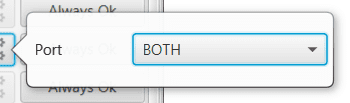
Output Filter configuration
CAN to Serial: This undoes the ‘Serial to CAN’ action, it has to be connected to I/O Setup producer.
Warning
For correct communication, mark it as High priority (with the Priority checkbox).
CAN Cmd: This is the input ESC expects to command RPM to the motor. It has to be connected to an Input Filter.
Warning
This configuration is already done by default. If the user changes this ID, make sure that the ID of the mailboxes also matches.
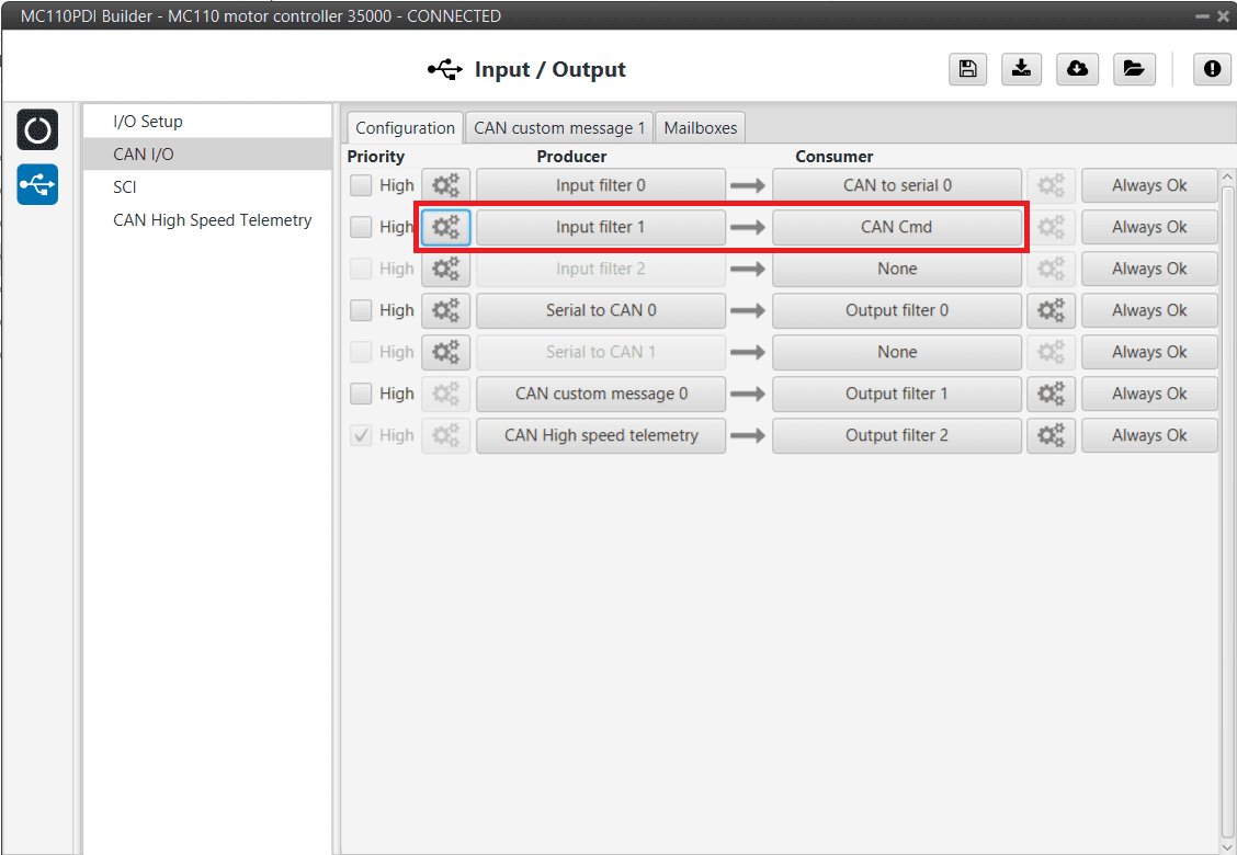
CAN configuration - CAN Cmd
CAN Cmd - Input filter configuration
CAN custom message
In the CAN custom message tab, the user chooses the variables to be sent over the CAN buses. The following elements can be configured:
TX Ini: Used to configure transmitted messages that are only sent once at the beginning of the operation (sent when the MC110 boots up). They can be used to initialize some devices.
TX: Used to configure transmitted messages.
Warning
The maximum capacity of a CAN message is 64 bits (8 bytes), so to send more information it must be divided into several messages.
MC110 has a CAN limitation of 40 TX messages and 40 TX Ini messages.
In addition, there is a limit shared with Serial Custom Messages:
Maximum number of vectors (fieldset): 104
Maximum number of fields: 2000
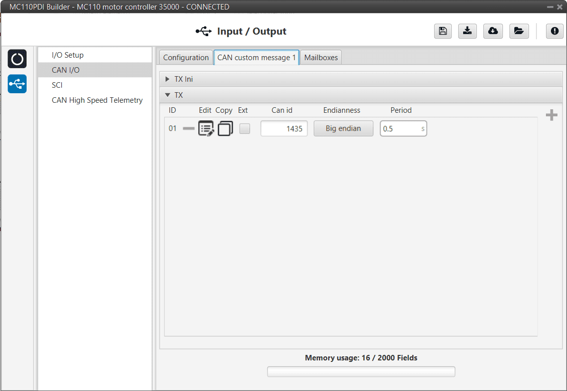
CAN custom message panel
Since this section works in a similar way to the CAN Custom Message configuration in the 1x PDI Builder software, the explanation to configure the telemetry messages via CAN can be found in the CAN Setup - Input/Output section of the 1x PDI Builder user manual.
Mailboxes
Main screen to configure baudrate and reception mailboxes of each CAN Bus.
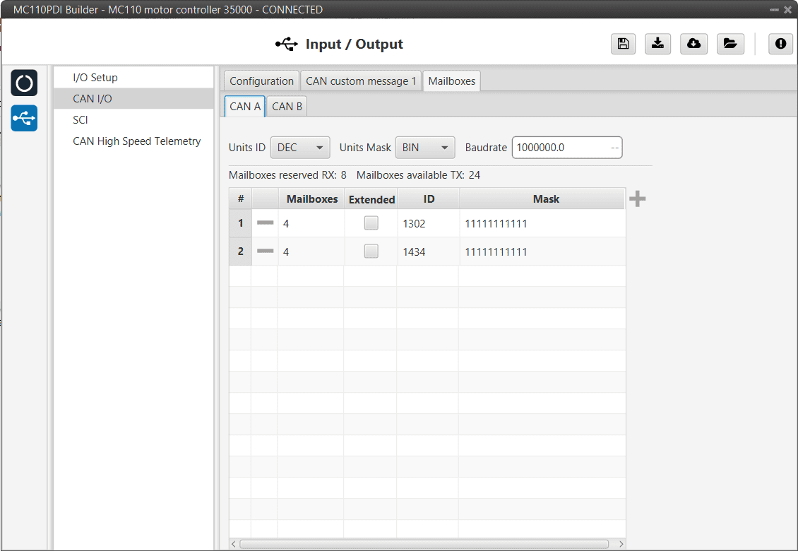
Mailboxes panel
More information about Mailboxes can be found in the Mailboxes - Input/Output section of the 1x PDI Builder user manual.
Furthermore, in the previous image it can be seen that there is a mailbox already configured with ID 1434. This is the mailbox that is associated with the CAN Cmd message, explained above, and that is configured by default.
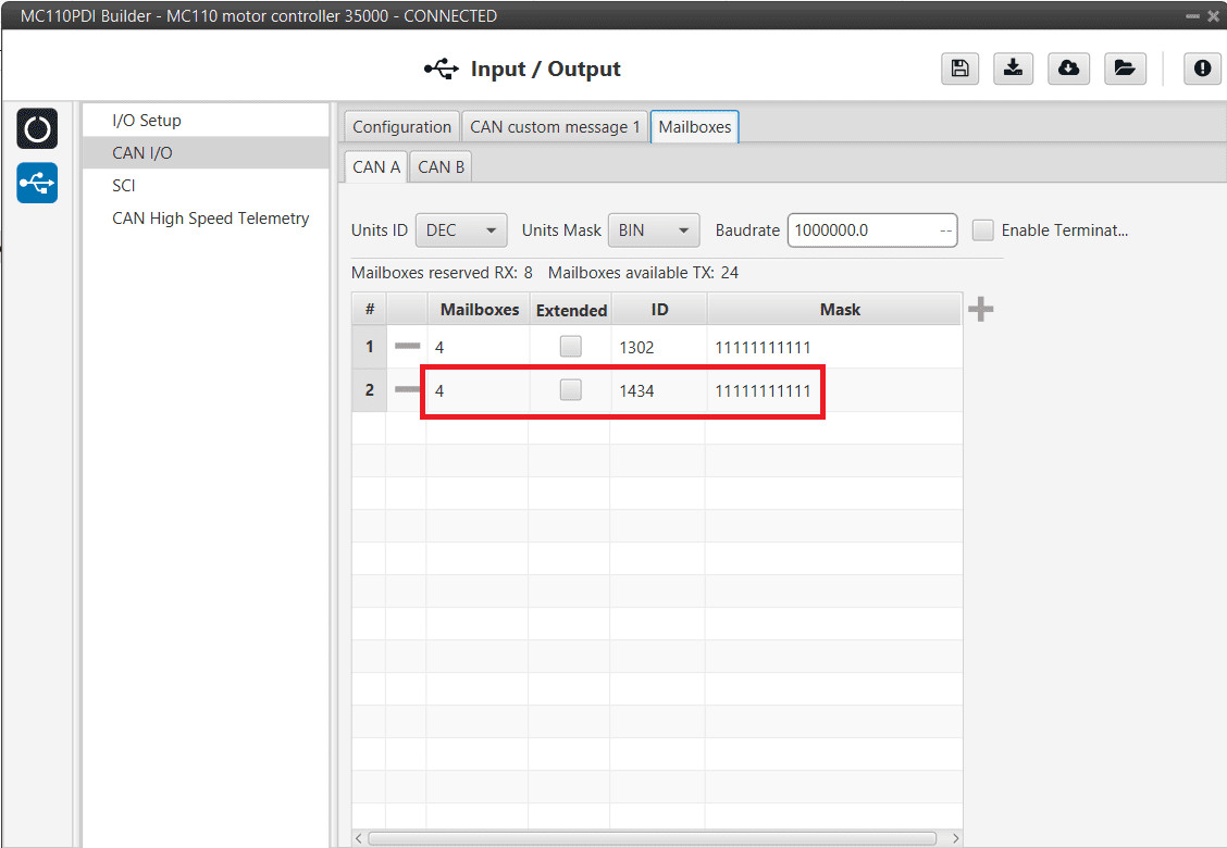
Mailboxes - CAN Cmd
SCI
MC110 can use up to three serial peripherals (SCI A, SCI B and SCI C). Serial ports A, B and C parameters can be edited in this menu to fit the serial protocol requirements.
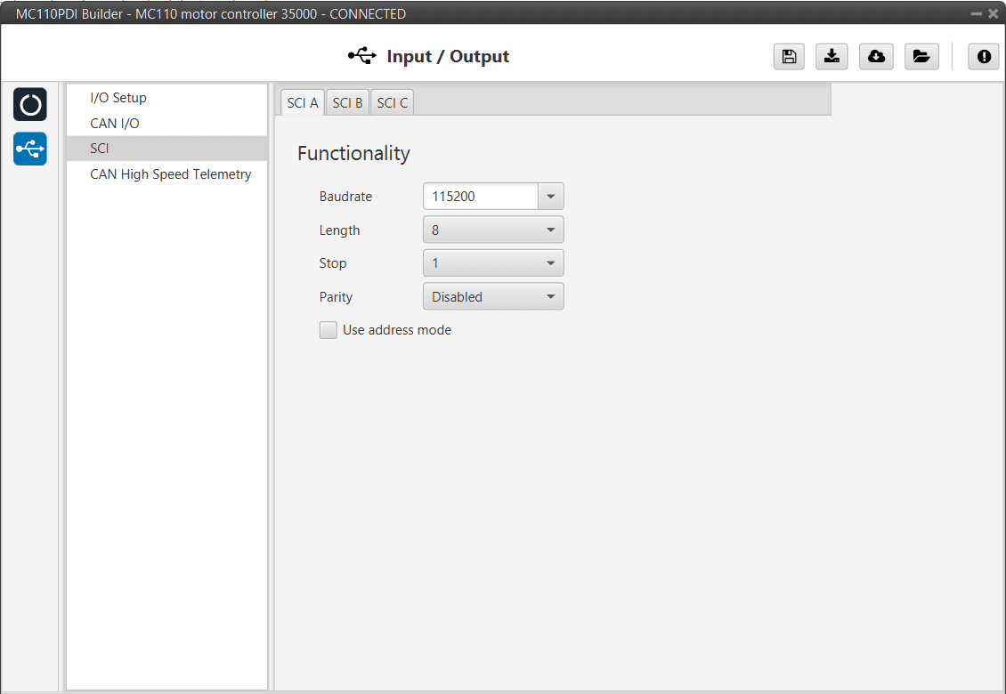
SCI panel
Baudrate: This field specifies how fast data is sent over a serial line.
Length: Defines the number of data bits for each character: 4 to 8 bits.
Stop: Number of stop bits sent at the end of each character: 1, 1.5 or 2.
Parity: Method to detect errors during transmission. When parity is used with a serial port, an extra data bit will be sent with each data character. The bits of each character (including parity bit) will be even or odd according to parity mode (odd, even or disabled).
Use address mode: 9-bit data framing uses the bit typically associated with parity error detection to identify address messages. Sent serial data that does not have the address bit set will be ignored (unless the device had previously identified an address message associated with it). This option can be disabled or enabled.
Note
SCI A corresponds to RS485 port, SCI B to RS232 port and SCI C to USB port.
CAN High Speed Telemetry
MC110 is equipped with special CAN telemetry, which is faster than the regular one. This is intended to monitor all RPM-dependent variables that can be crucial for tuning the user’s ESC during the initial stages.
For instance, seeing the electrical angle can be extremely difficult with a low sampling rate at high RPMs and as a consequence, tuning the observer gain can be difficult. Similarly, monitoring the current being measured in each phase can present the same problem and make PI tuning very time consuming.
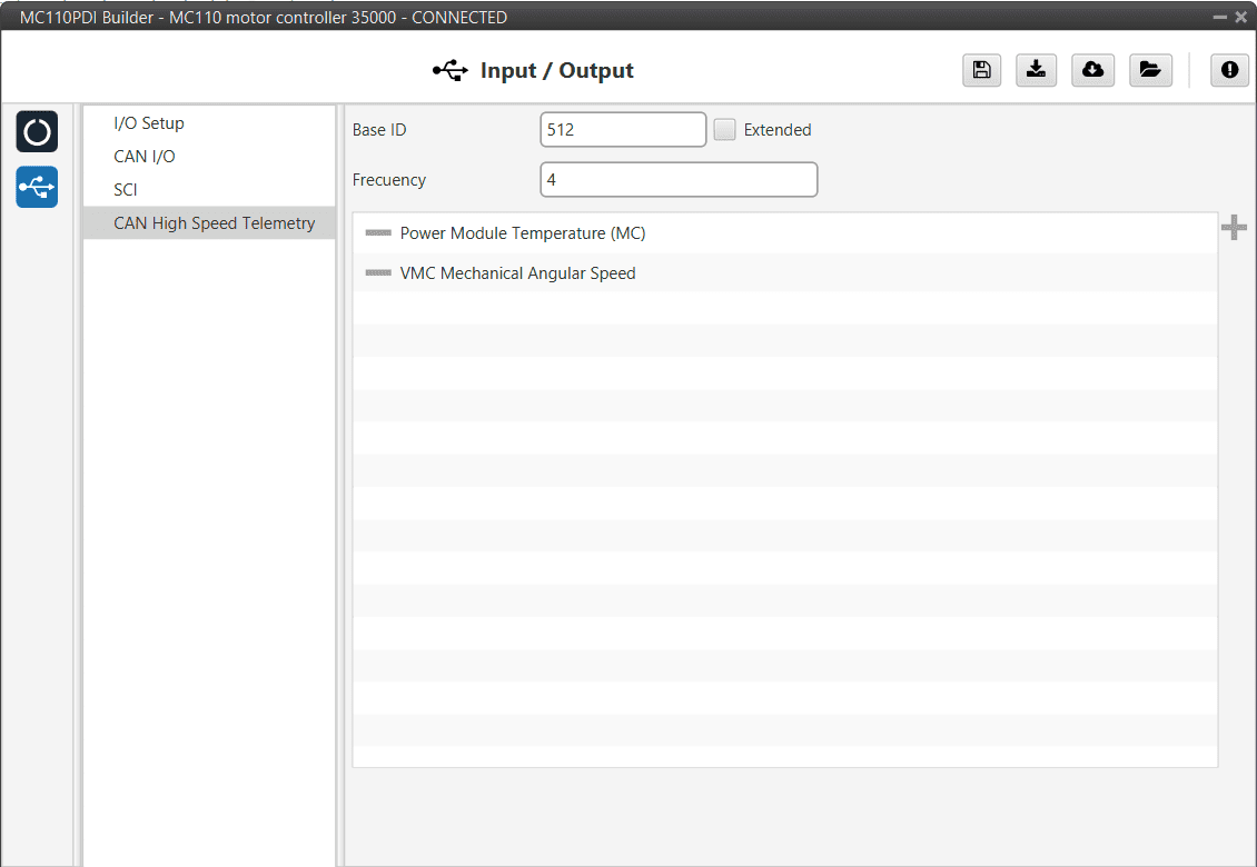
CAN High Speed Telemetry panel
Only two parameters need to be configured here:
Base ID: This is the CAN Id associated with the first variable in the list to be used. Subsequent IDs will be reserved according to the variable list.
Extended: If enabled, the frame format will be ‘Extended’, i.e. with a 29-bit identifier. Otherwise, the frame format ‘Standard’ (11-bit identifier) is set by default.
Frequency (decimation): The number of clock steps the ESC skips before sending a High Speed CAN telemetry packet.
Note
A separate tool is offered to see MC telemetry \(\Rightarrow\) CAN Telemetry, please contact sales@embention.com.