Technical
Variants
Veronte MC01 has to variants or versions. Both have the same hardware, nonetheless the software is different.
MC01B - Brushless variant: for brushless motors.
MC01S - Stepper variant: for stepper motors.
General features
Compact design
Lightweight
Low energy consumption
Very quick reaction
Support for encoders
Gyro-stabilisation
Control algorithm: Proportional Integral Derivative (configurable gains)
Dimensions: 60x25x15mm
Weight: 10g
Redundant Isolated CAN Expansion
2x CAN for critical actuators - two wires each one
No power wires required (optional)
Auxiliary Power Outputs
1x 5V DC
1x 3.3V DC
Embedded Sensors
Input voltage
Board temperature
Communication buses
1x CAN
1x I2C
Input / Output
4x GPIO (on/off)
2x PWM / ECAP
Supported encoders
SPI Differential
SPI
Digital (ECAP and EQEP)
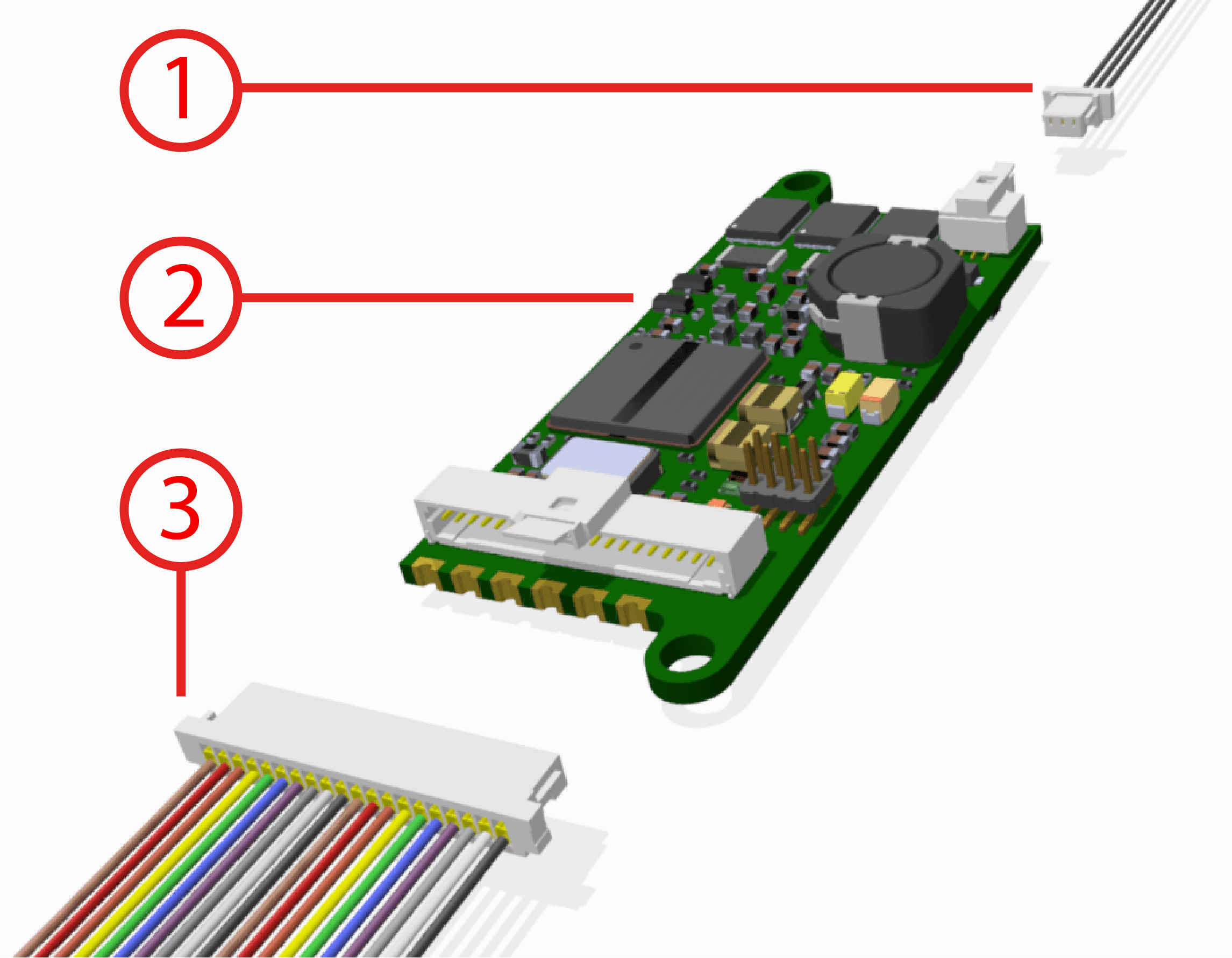
Part List

Number |
Description |
Commercial reference |
|---|---|---|
1 |
Connector with 3 pins |
S1SS-03-28-GF-07_00-L |
2 |
Veronte MC01 controller |
|
3 |
Connector with 20 pins |
S1SS-20-28C-GF-11_00-L |
Dimensions

Veronte MC01 board dimensions
Electrical specifications
Motor
Voltage: same as input. 3-phase brushless interface.
EQEP encoder
32-bit QEP channels.
PWM/ECAP
Maximum voltage: 3.3V.
Maximum input current: 2.5 mA.
Sampling rate: up to 1 micro s.
Auxiliary 3.3V output
Non-protected output - Light loads.
Auxiliary 5V output
Non-protected output - Light loads.
CAN
Complies with standards.
Non-Isolated.
Speed up to 1 Mbps.
I2C
3.3V Signals up to 400 KHz.
Power Input
Vmax = 24V DC.
IMax: 3A. Depends on the motor.
Inom: 0.3A (motor not working).
Typical Input Current: 1.5A.
SPI encoder
Maximum and minimum voltage: +12 to -12V.
Addon for isolated CAN transceivers - New board soldered.
Interfaces
The only connections required are the connectors shown in the Part List section.
