Software Installation
A simple web application, VSE Application, allows the user to customize the number of channels and their output signals.
Web VSE Application
To open this VSE Application it is necessary to follow these steps:
Connect the VSE:
To the USB Joystick through USB.
To power supply.
In the computer, click the Network icon and connect to the WiFi network named VSE-0XXX.
Note
VSE network may need a few seconds to be displayed.
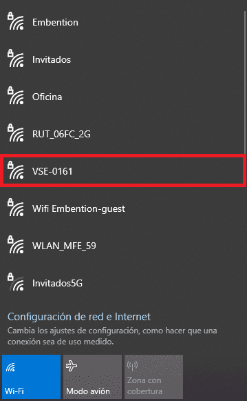
Select WiFi network
Enter the WiFi password: giy77uHQvOROoMoLEwKK.
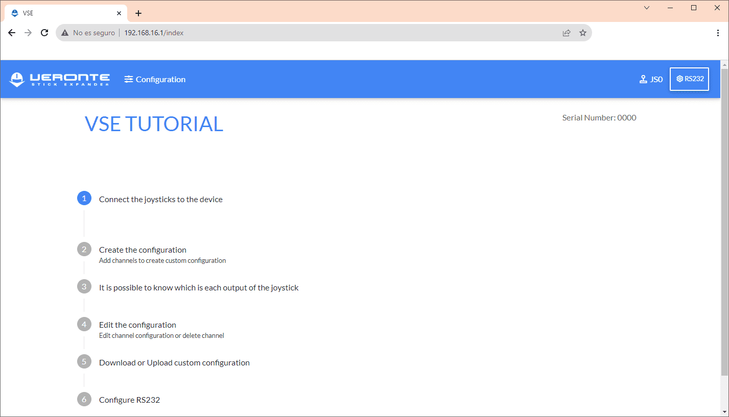
Once connected to the network, open the browser and go to the page http://192.168.16.1.
Configuration
This section explains in detail all the features of VSE Application.
Channels
Once in the application, to configure the channels:
Click in Configuration.
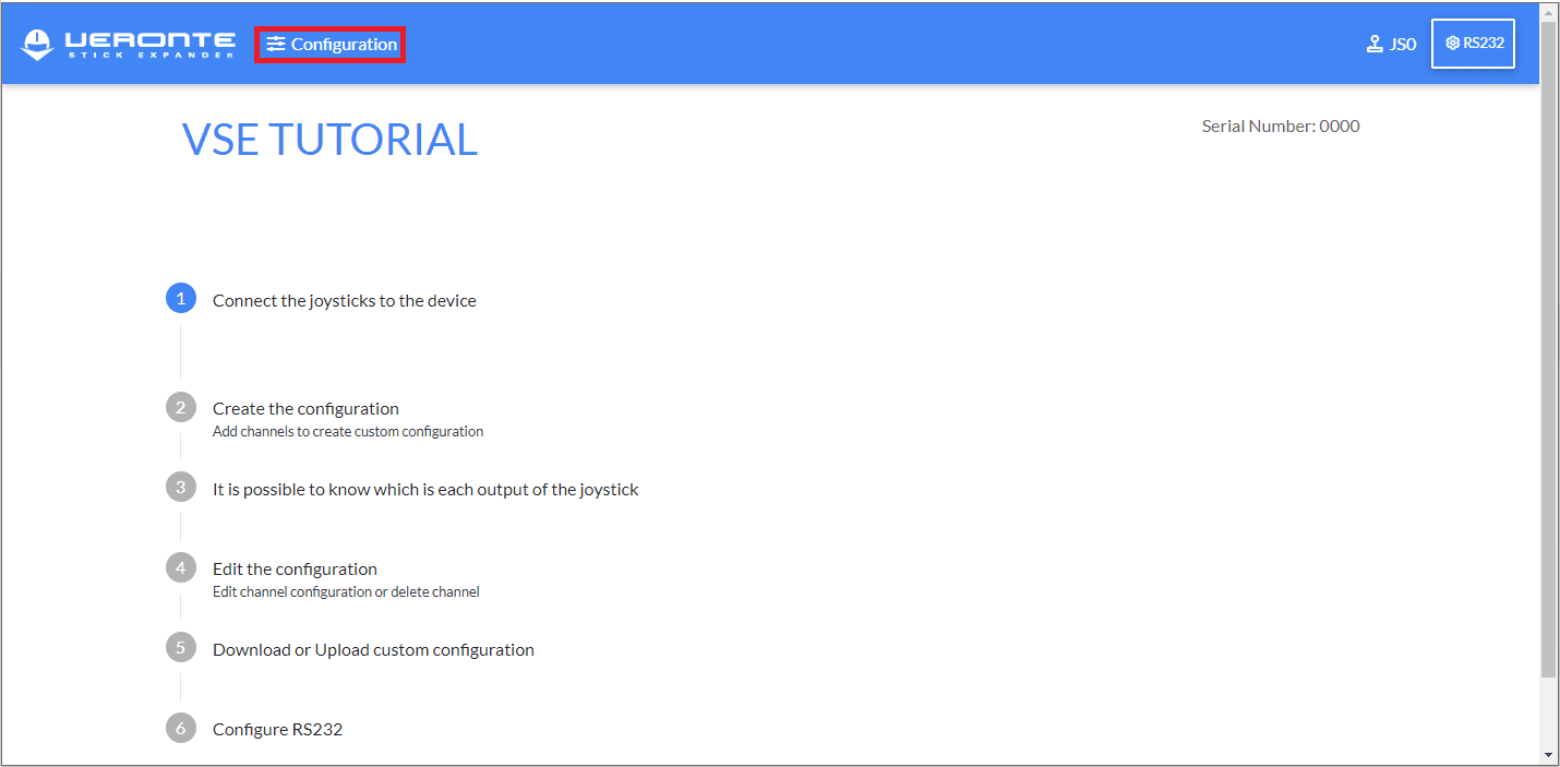
Configuration
Click in Add Channel button.
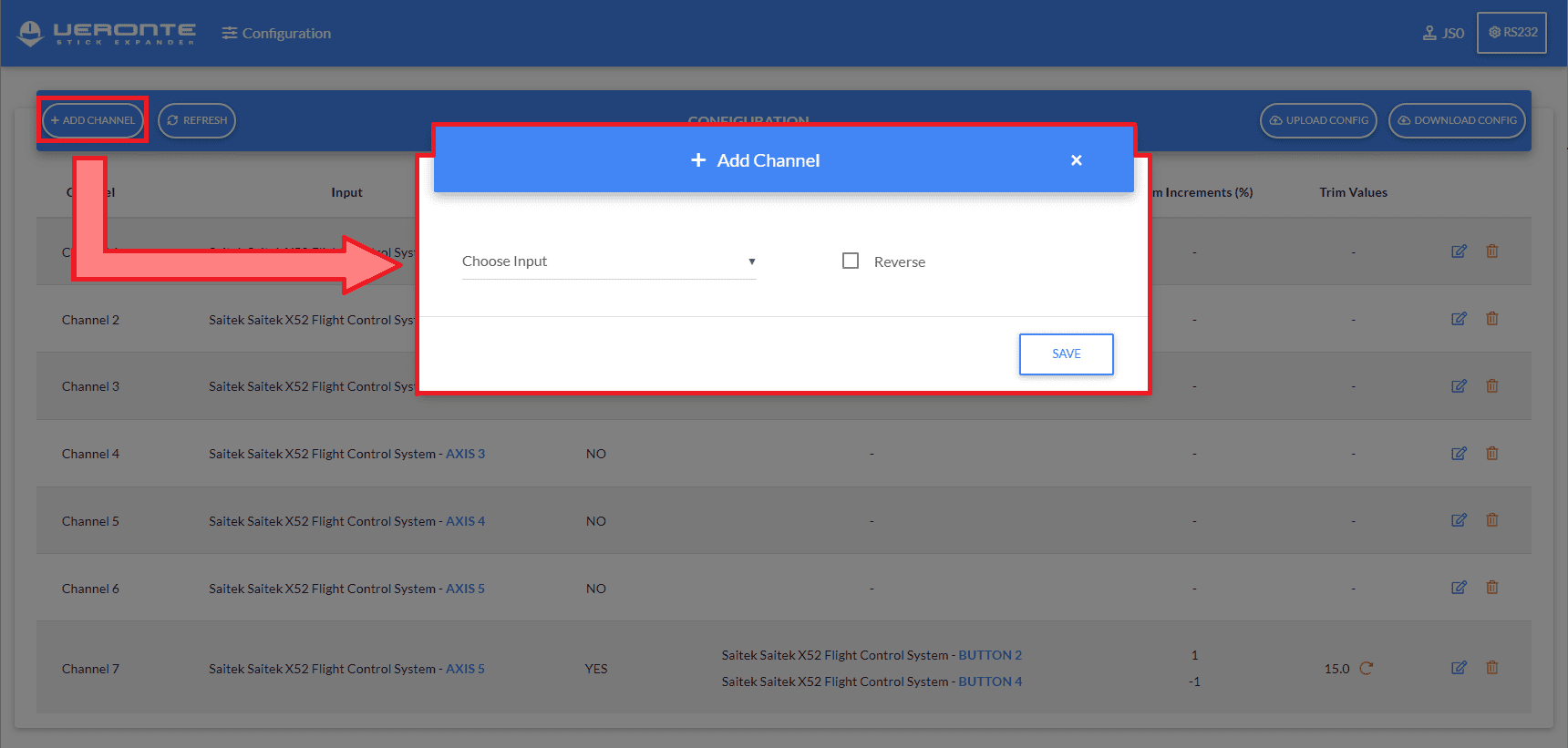
Add Channel
Configure the channel as preferred:
Choose Input: Select joystick input (axes or button).
Reverse: Tick this checkbox to reverse the selected input.
Trim: Users can select which button to press to trim the raw value of the selected axis. Each click of the selected button will apply the following Trim equation to the axis output signal:
\[Final \; trimmed \; value = Initial \; Stick \; Input \; value \; + \left(\frac{Increment(\%)}{100} \times Initial \; Stick \; Input \; value \right)\]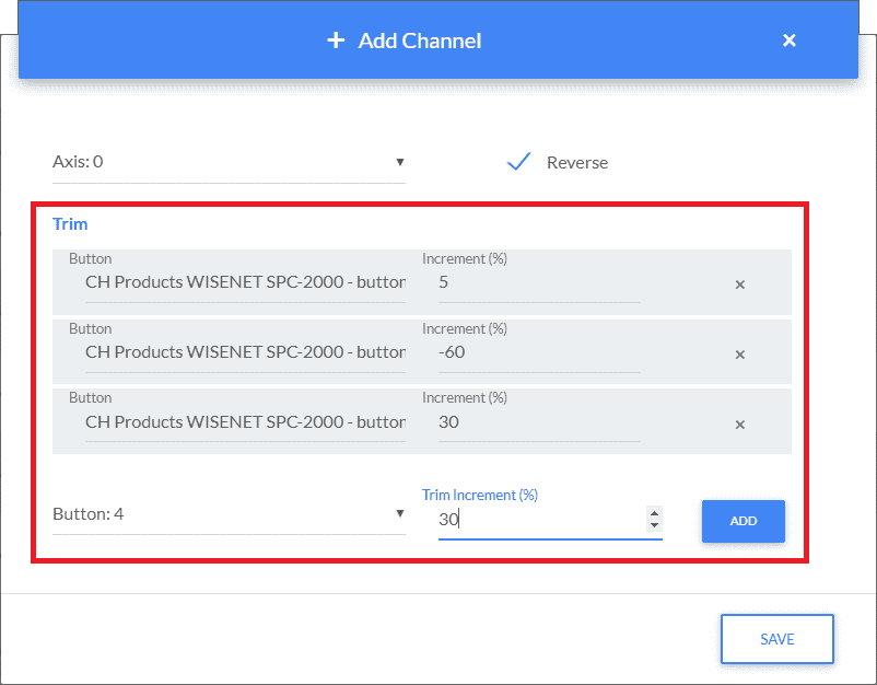
Trim parameters
Choose button: Select the button which will trim the input value.
Trim Increment (%): Percentage value used to calculate the trimed value.
Note
Trim Increment can be positive or negative.
Add: Saves the configured trimming button.
Note
It is possible to add N customized trimming buttons to each axis, which will be listed in the Trim section of this Add Channel panel.
Example:
Initial Stick Input (r1)
Trim Increment
Trimmed Stick Input (rounded)
0.49
10%
0.54
Save the configured channel.
The configuration parameters of the created channel are displayed in the following list:
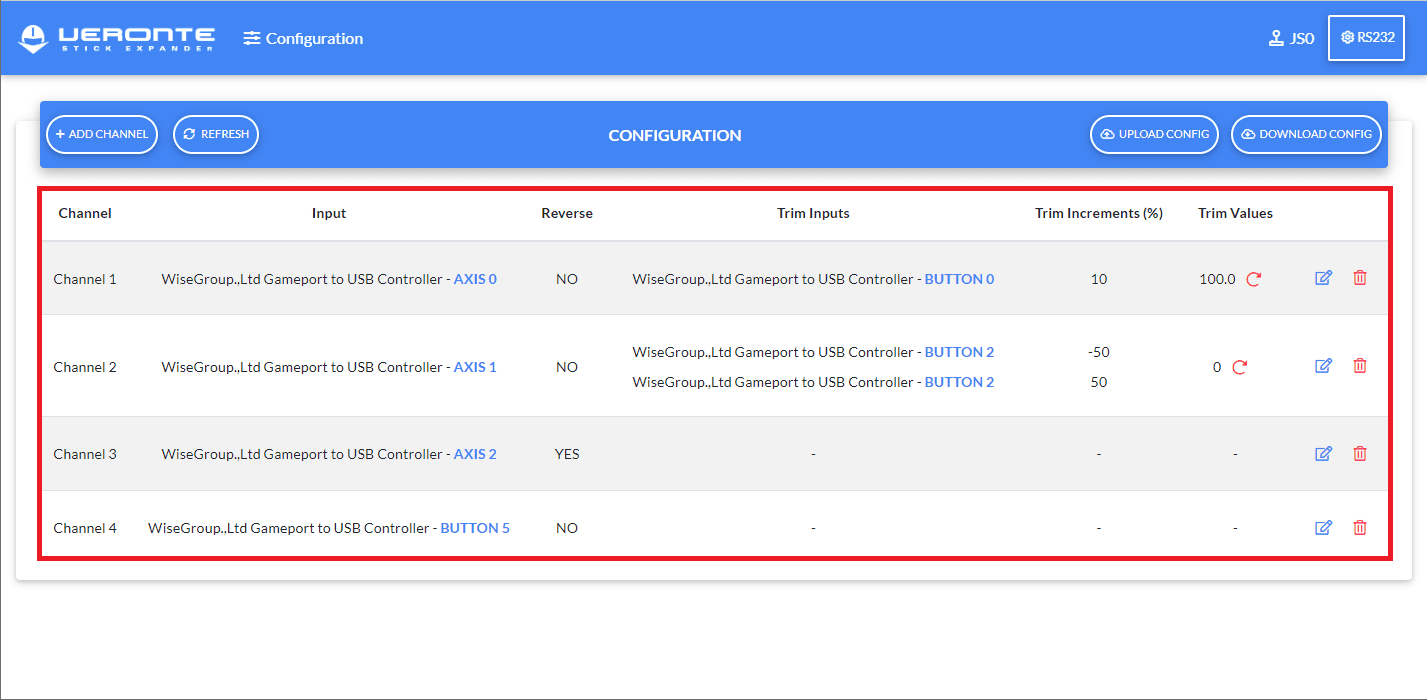
Users can edit these parameters with Channels buttons.
Joystick Output View
To make easier the configuration of channels, the application shows the output values of every connected joystick.
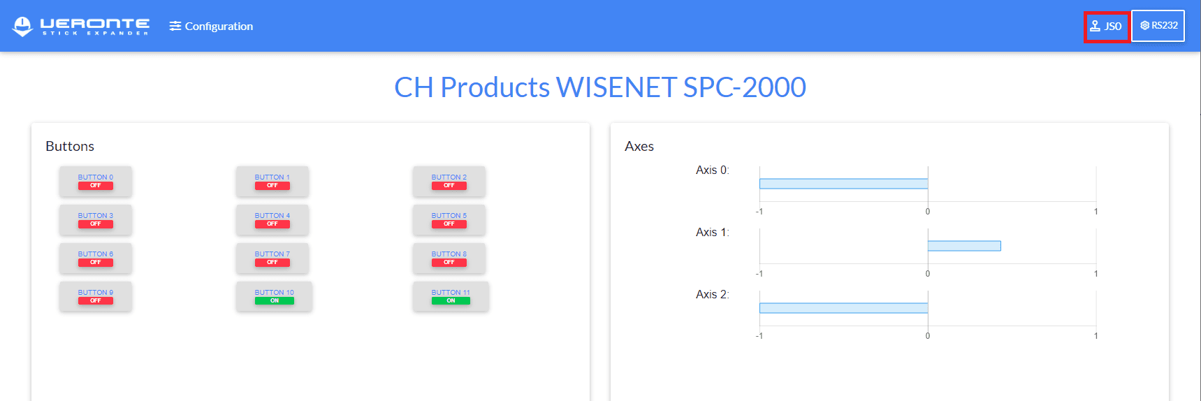
Joystick View
Joystick buttons are represented with ON or OFF status and the axes with their values between [-1, 1].
PPM Configuration in 1x PDI Builder
To properly use the VSE solution, it is important to configure the PPM inputs in Veronte Autopilot 1x using 1x PDI Builder app. Users must perform the configuration corresponding to a PPM Stick, explained in further detail in VSE (Veronte Stick Expander) - Integration Examples section of the 1x PDI Builder user manual.
The figure below shows the PPM signal that arrives to Veronte:
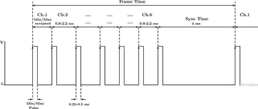
PPM Pulses