Veronte products
Autopilot 4x
Arbiters communication
To establish on a Veronte Autopilot 4x hwv 1.8 the communication between Autopilots 1x and Arbiters via CAN, the following connection is required:
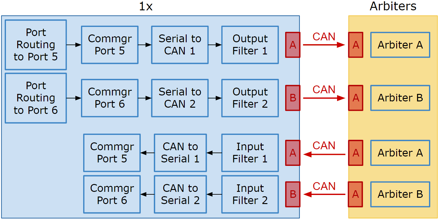
Communication diagram 1x \(\leftrightarrow\) Arbiters
Follow the steps below to make this configuration:
Go to Communications menu \(\rightarrow\) Ports panel.
Remove Port 5 and 6 from the Forward group and add Port 5 and 6 to the Route group, with target Arbiters’ Address:
Address of Arbiter A: 50 000 + Serial number
Address of Arbiter B: 54 000 + Serial number
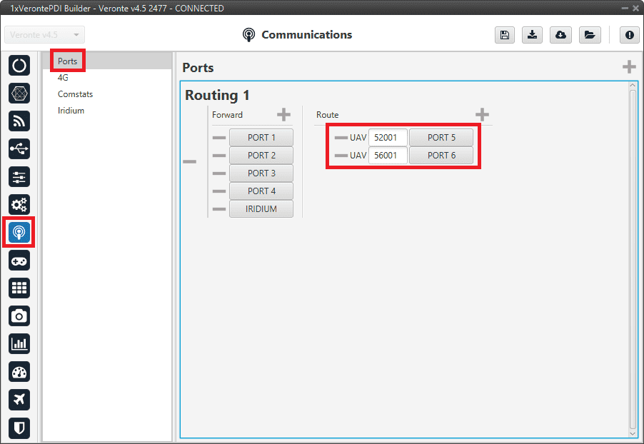
Arbiters communication - Routing configuration
Note
This is just an example, users can choose Ports other than 5 and 6.
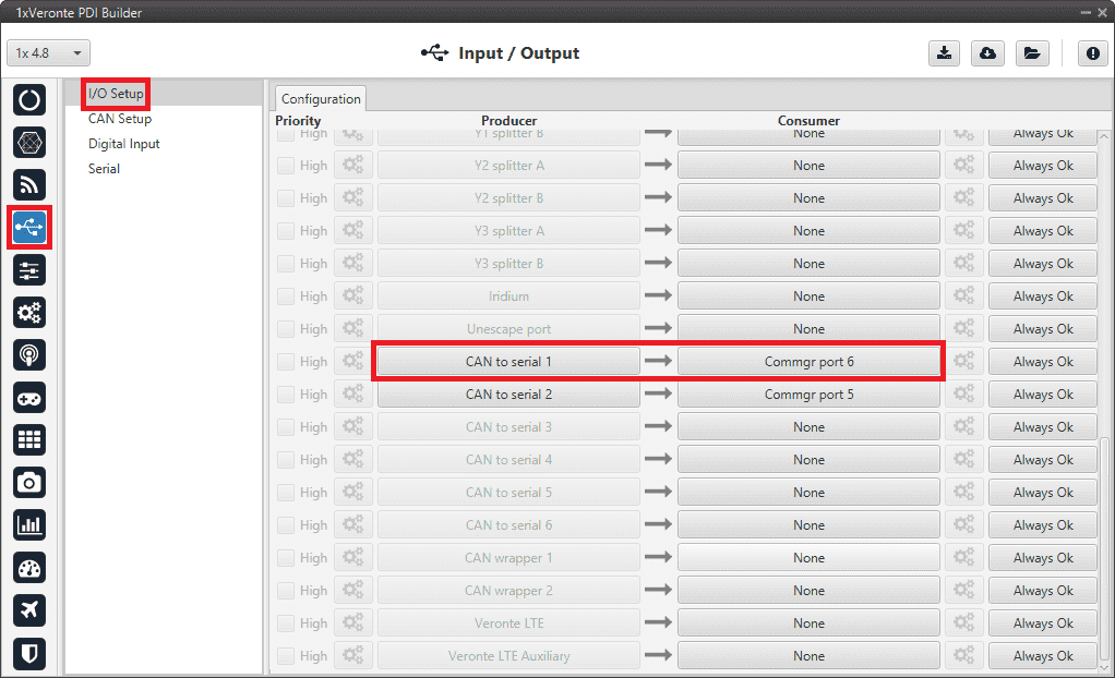
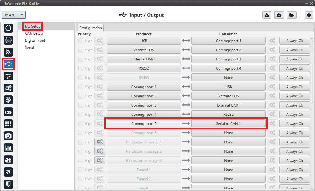
Go to Input/Output menu \(\rightarrow\) I/O Setup panel.
Connect Commgr port 5 to Serial to CAN 1 consumer and Commgr port 6 to Serial to CAN 2 consumer:
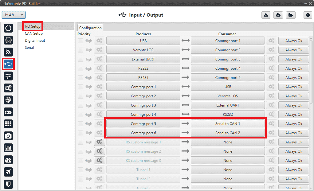
Arbiters communication - I/O Setup configuration: Serial to CAN
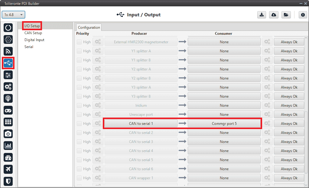
Then, connect CAN to serial 1 to Commgr port 5 and CAN to serial 2 to Commgr port 6:
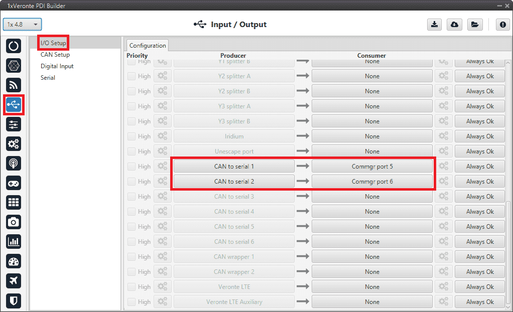
Arbiters communication - I/O Setup configuration: CAN to serial
Note
This is just an example, users can choose Serial to CAN and CAN to serial other than 1 and 2.
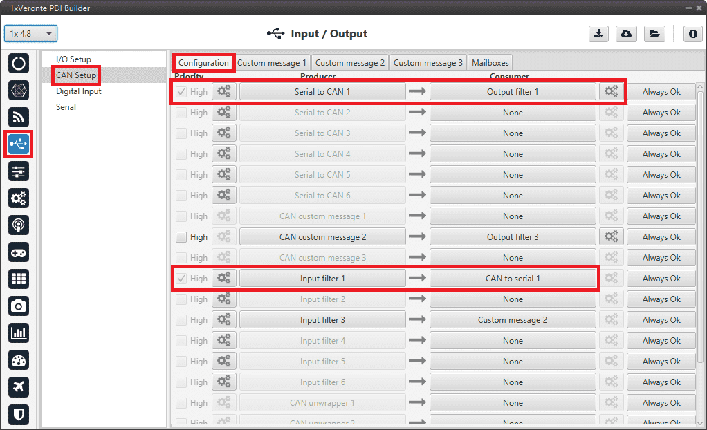
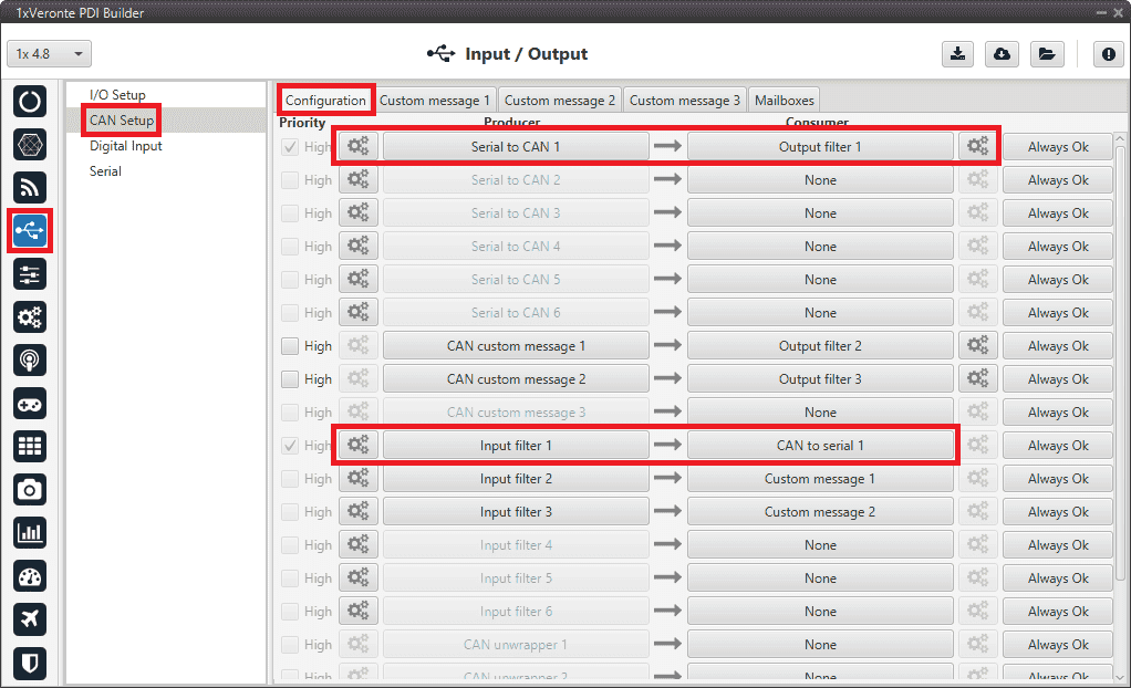
Go to Input/Output menu \(\rightarrow\) CAN Setup panel \(\rightarrow\) Configuration tab.
Connect Serial to CAN 1 to Output filter 1 and Serial to CAN 2 to Output filter 2.
In addition, connect Input filter 1 to CAN to serial 1 and Input filter 2 to CAN to serial 2:
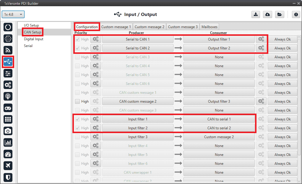
Arbiters communication - CAN Setup configuration
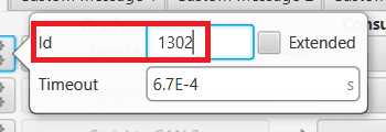
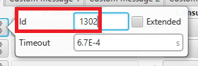
Set for both Serial to CAN 1/2 the same CAN ID: 1302.
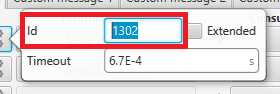
Arbiters communication - Serial to CAN 1/2 configuration
Select for Output filter 1 the CAN A, as this is the CAN of Autopilot 1x that is connected to Arbiter A:
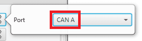
Arbiters communication - Output filter 1 configuration
Select for Output filter 2 the CAN B, as this is the CAN of Autopilot 1x that is connected to Arbiter B:
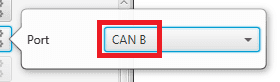
Arbiters communication - Output filter 2 configuration
Configure both Input filter 1/2 with CAN ID: 1301.
Select for Input filter 1 the CAN A, as this is the CAN of Autopilot 1x that is connected to Arbiter A:
Arbiters communication - Input filter 1 configuration
Select for Input filter 2 the CAN B, as this is the CAN of Autopilot 1x that is connected to Arbiter B:
Arbiters communication - Input filter 2 configuration
Note
This is just an example, users can choose Input filter and Output filter other than 1 and 2.
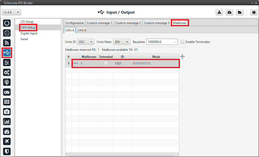
Go to Input/Output menu \(\rightarrow\) CAN Setup panel \(\rightarrow\) Mailboxes tab.
Set the Baudrate for both CANs, CAN A: 1 000 000 and CAN B: 500 000.
Configure at least 10 reception mailboxes with ID 1301 for both CAN A and B:
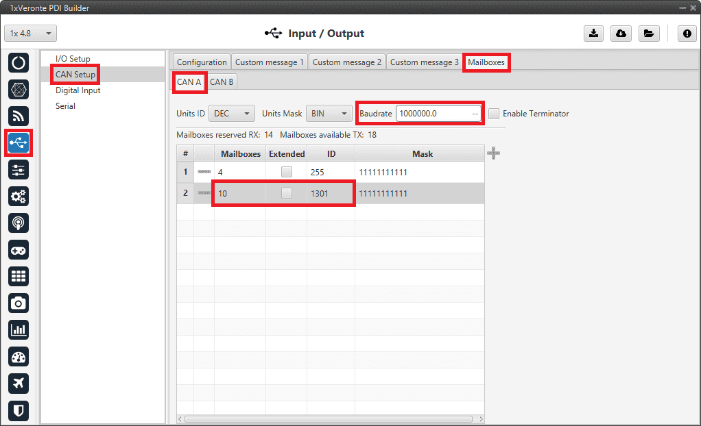
Arbiters communication - Mailboxes configuration: CAN A
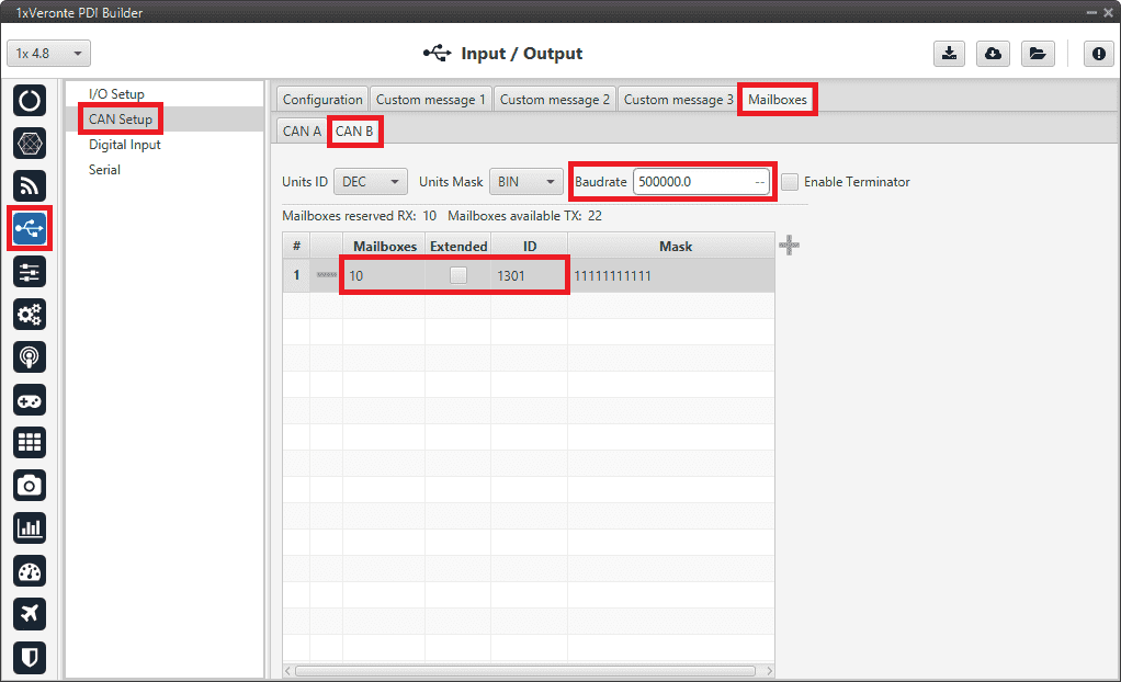
Arbiters communication - Mailboxes configuration: CAN B
CEX/MEX
As it is sometimes not possible to connect a CEX/MEX directly to the PC in order to configure it (access CEX/MEX PDI Builder), the Veronte Autopilot 1x is connected to the computer and a connection is made between CEX/MEX and Veronte Autopilot 1x via CAN.
To be able to communicate with CEX/MEX via CAN, the following connection is necessary:
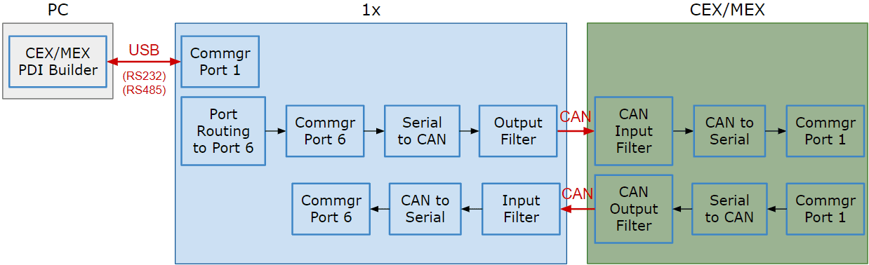
Communication diagram 1x \(\leftrightarrow\) CEX/MEX
Note
1x usually has this configuration by default, but check it out.
As the steps to be performed in CEX PDI Builder and MEX PDI Builder are exactly the same, only the steps for one of them will be detailed. The interface may differ slightly, but the configuration is the same.
Follow the steps below to make this configuration:
1x PDI Builder side
Go to Input/Output menu \(\rightarrow\) I/O Setup panel.
Check the connection between the computer and the 1x (usually via USB, but RS232 and RS485 are also possible).
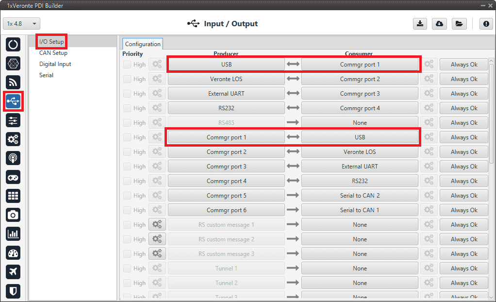
1x PDI Builder - I/O Setup configuration
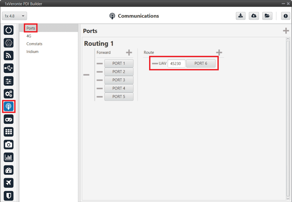
Go to Communications menu \(\rightarrow\) Ports panel.
Remove Port 6 from the Forward group and add Port 6 to the Route group, with target CEX’s Address:
\(\Rightarrow\) Address = 44000 + Serial number.
The CEX address must be in the range 45000 - 49999.
Note
For MEX, the address should look like this:
Address = 42000 + Serial number.
The MEX address must be in the range 43000 - 43999.
If the theorical address does not work, 999 (unknown) can be used as sometimes the address has not been set in CEX/MEX.
1x PDI Builder - Routing configuration
Go to Input/Output menu \(\rightarrow\) I/O Setup panel.
Connect Commgr port 6 to Serial to CAN 1 consumer:
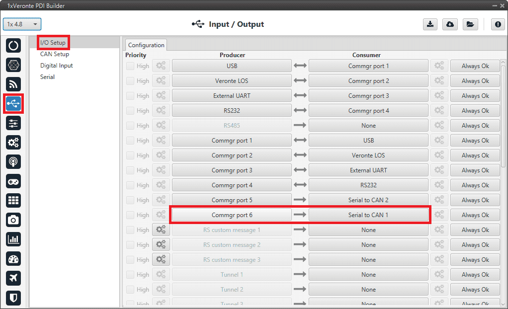
1x PDI Builder - I/O Setup configuration: Serial to CAN
Then, connect CAN to serial 1 to Commgr port 6:
1x PDI Builder - I/O Setup configuration: CAN to serial
Go to Input/Output menu \(\rightarrow\) CAN Setup panel \(\rightarrow\) Configuration tab.
Connect a Serial to CAN with the right Id (CAN ID 1302) to an Output filter.
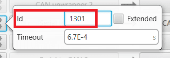
In addition, connect an Input filter with the right Id (CAN ID 1301) to a CAN to serial:
1x PDI Builder - CAN Setup configuration
1x PDI Builder - Serial to CAN configuration
1x PDI Builder - Input filter configuration
Go to Input/Output menu \(\rightarrow\) CAN Setup panel \(\rightarrow\) Mailboxes tab.
Finally, configure the reception mailbox with ID 1301, assign at least 4 mailboxes:
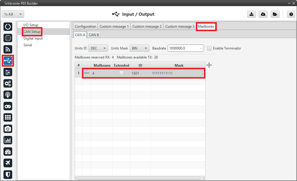
1x PDI Builder - Mailboxes configuration
CEX PDI Builder side
Note
This part is already built for CEX default configuration, but the user can check it.
Go to Input/Output menu \(\rightarrow\) CAN I/O panel \(\rightarrow\) Configuration tab.
Connect a CAN Input Filter with the right CAN Address (CAN ID 1302) to CAN to Serial 0.
In addition, connect Serial to CAN 0 with the right CAN Address (CAN ID 1301) to a CAN Output Filter port:
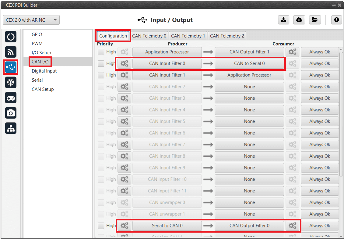
CEX PDI Builder - CAN I/O configuration
CEX PDI Builder - CAN Input Filter configuration
CEX PDI Builder - Serial to CAN configuration
Go to Input/Output menu \(\rightarrow\) I/O Setup panel.
Connect CAN to Serial 0 to any Commgr port, in this case Commgr port 0 is used.
In addition, connect Commgr port 0 to Serial to CAN 0 consumer:
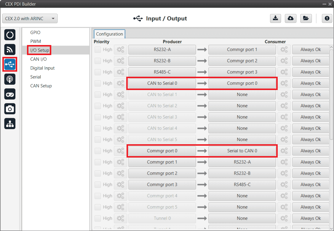
CEX PDI Builder - I/O Setup configuration
Go to Input/Output menu \(\rightarrow\) CAN Setup panel.
Finally, configure the reception mailbox with ID 1302, assign at least 4 mailboxes:
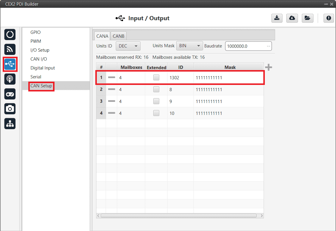
CEX PDI Builder - CAN Setup (Mailboxes) configuration
MC01
In order to communicate a Veronte Autopilot 1x with a MC01 via CAN, the following connection is required:
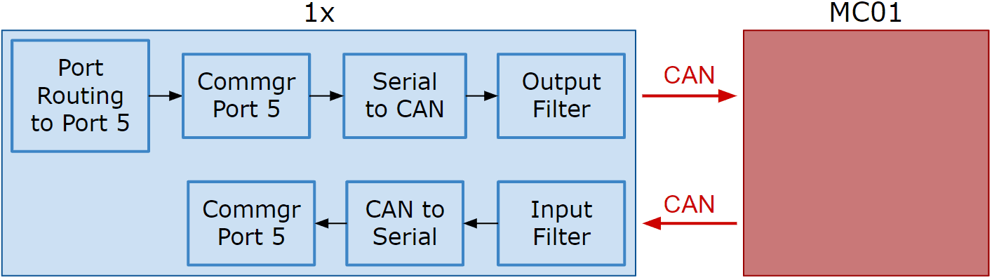
Communication diagram 1x \(\leftrightarrow\) MC01
The following steps explain how to configure the communication between an Autopilot 1x and a MC01.
MC01 PDI Builder side
By default, MC01 is configurated with a connection Serial to CAN, with the following Standard CAN IDs:
Tx CAN Id: 1301
Rx CAN Id: 1302
1x PDI Builder side
Go to Communications menu \(\rightarrow\) Ports panel.
Remove Port 5 from the Forward group and add Port 5 to the Route group, with target MC01’s Address. This address must be chosen in the destination path of the MC01 (40117 for the example).
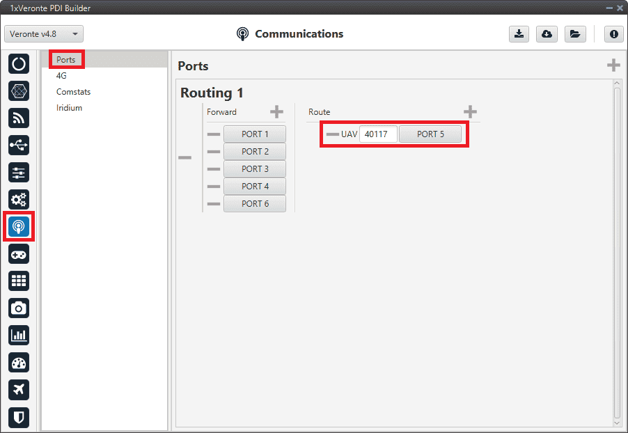
1x PDI Builder - Routing configuration
Go to Input/Output menu \(\rightarrow\) I/O Setup panel.
Connect the Commgr port 5 to the Serial to CAN 1.
1x PDI Builder - I/O Setup configuration: Serial to CAN
Then, connect CAN to serial 1 to Commgr port 5:
1x PDI Builder - I/O Setup configuration: CAN to serial
Go to Input/Output menu \(\rightarrow\) CAN Setup panel \(\rightarrow\) Configuration tab.
Connect a Serial to CAN with the right Id (CAN ID 1302) to an Output filter.
In addition, connect an Input filter with the right Id (CAN ID 1301) to a CAN to serial:
1x PDI Builder - CAN Setup configuration
1x PDI Builder - Serial to CAN configuration
1x PDI Builder - Input filter configuration
Go to Input/Output menu \(\rightarrow\) CAN Setup panel \(\rightarrow\) Mailboxes tab.
Finally, configure the reception mailbox with ID 1301, assign at least 1 mailbox:
1x PDI Builder - Mailboxes configuration
MC110/MC24
In order to send commands from a Veronte Autopilot 1x to a MC110/MC24 via CAN and vice versa, the following connection is required:
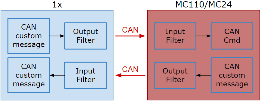
Communication diagram 1x \(\leftrightarrow\) MC110/MC24
Note
As the steps to be performed in MC110 PDI Builder and MC24 PDI Builder are exactly the same, only the steps for one of them will be detailed. The interface may differ slightly, but the configuration is the same.
CAN commands from Autopilot 1x to MC110
Follow the steps below to make this configuration:
1x PDI Builder side
Go to Input/Output menu \(\rightarrow\) CAN Setup panel \(\rightarrow\) Configuration tab.
Connect a CAN custom message producer (in this case CAN custom message 1 is used) to an Output filter consumer, in this example Output filter 3.
In addition, configure the Output filter with the correct CAN Bus, in this example CAN A has been selected:
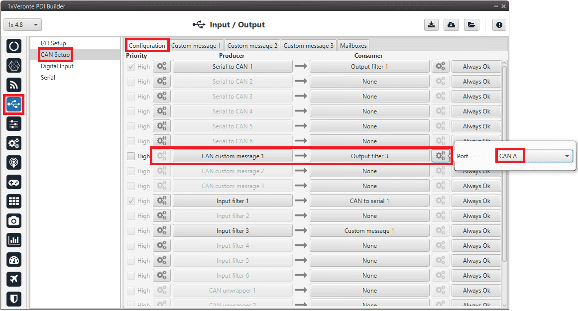
1x PDI Builder - CAN Setup configuration
Go to Input/Output menu \(\rightarrow\) CAN Setup panel \(\rightarrow\) Custom message 1 tab (since the producer CAN custom message 1 has been connected to the output filter).

Add a new message in TX (as it is for tranmission) with CAN ID 1434. More information on the configuration of CAN messages can be found in the TX/TX Ini Messages (Custom Messages) - Input/Output section of this manual.
Next, configure the message to be sent with whatever variable users wish to use to command. The variable should be set to compressed signed 32-bit.
Users should send the values from 0 to max_rpm (or from -max_rpm to max_rpm if negative commands are desired to be allowed).
To do this, it is recommended to control the variable internally as a throttle, for this set the Encode from 0 to 1 (or from -1 to 1 for negative speeds). And for decode it to rpm values, the Decode parameter must be configured from 0 to max_rpm (or from -max_rpm to max_rpm if negative commands are allowed):
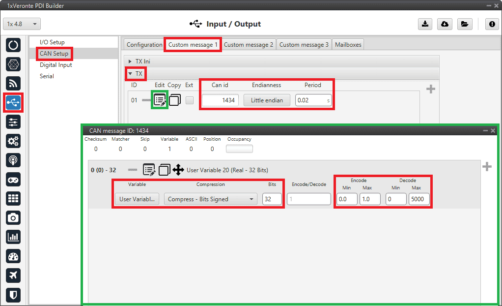
1x PDI Builder - CAN custom message 1 configuration
For more information on configuring CAN custom messages, refer to the Custom Messages types - Input/Output section of this manual.
Warning
Remember that it is necessary to have at least 1 free mailbox for TX messages.
MC110 PDI Builder side
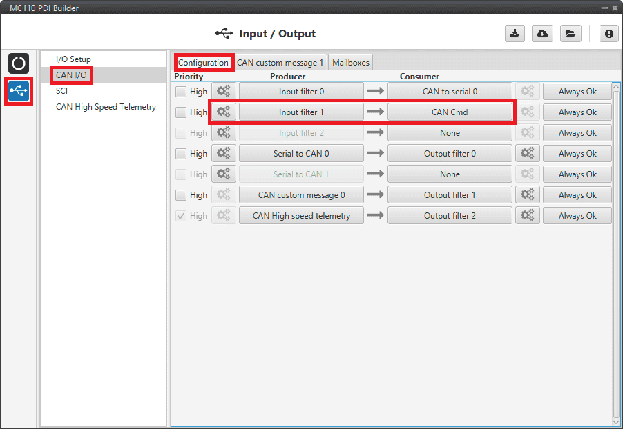
Go to Input/Output menu \(\rightarrow\) CAN I/O panel \(\rightarrow\) Configuration tab.
Connect an Input filter producer, in this example Input filter 1, to the CAN Cmd consumer.
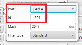
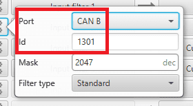
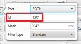
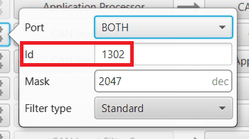
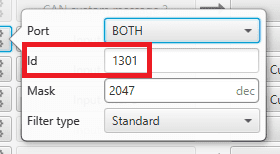
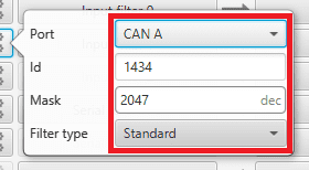
In addition, configure the input filter with the following parameters:
Port: CAN A
CAN Id 1434
Mask: 2047 dec
Filter type: Standard
MC110 PDI Builder - CAN I/O configuration
MC110 PDI Builder - Input filter configuration
Go to Input/Output menu \(\rightarrow\) CAN I/O panel \(\rightarrow\) Mailboxes tab.
Configure at least 4 reception mailboxes with ID 1434 in the CAN A bus:
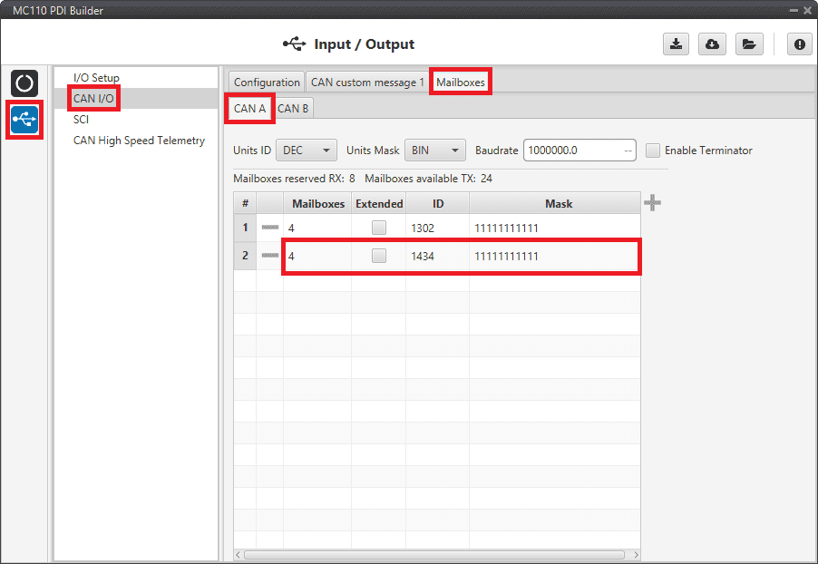
MC110 PDI Builder - Mailboxes configuration
Go to MC menu \(\rightarrow\) FOC Control panel \(\rightarrow\) Control Input.
Make sure that m_CAN or m_CAN_PPM mode is selected.
For more information on these parameters, refer to the Control Input (FOC Control) - MC section of MC110 PDI Builder user manual.
CAN commands from MC110 to Autopilot 1x
Follow the steps below to make this configuration:
MC110 PDI Builder side
Go to Input/Output menu \(\rightarrow\) CAN I/O panel \(\rightarrow\) Configuration tab.
Connect CAN custom message 0 producer to an Output filter consumer, in this example Output filter 1.
In addition, configure the Output filter with the correct CAN Bus, in this example CAN A has been selected:
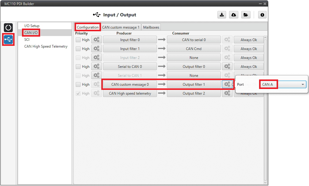
MC110 PDI Builder - CAN I/O configuration
Go to Input/Output menu \(\rightarrow\) CAN I/O panel \(\rightarrow\) CAN custom message 1 tab.
Add a new message in TX with the variables the user wishes to send back to Autopilot 1x.
In this example, the message with CAN ID 100 is sending the input command value as well as the board temperature as uncompressed variables.
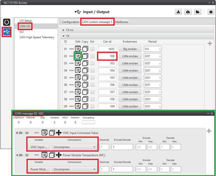
MC110 PDI Builder - CAN custom message 1 configuration
For more information on configuring CAN custom messages, refer to the Custom Messages types - Input/Output section of this manual.
Note
If the variables are compressed/encoded on the MC110 side when sent, they must be decompressed/decoded on the Autopilot 1x unit on reception.
1x PDI Builder side
Go to Input/Output menu \(\rightarrow\) CAN Setup panel \(\rightarrow\) Configuration tab.
Connect an Input filter producer (in this case Input filter 3) to a Custom message consumer (Custom message 1 has been selected).
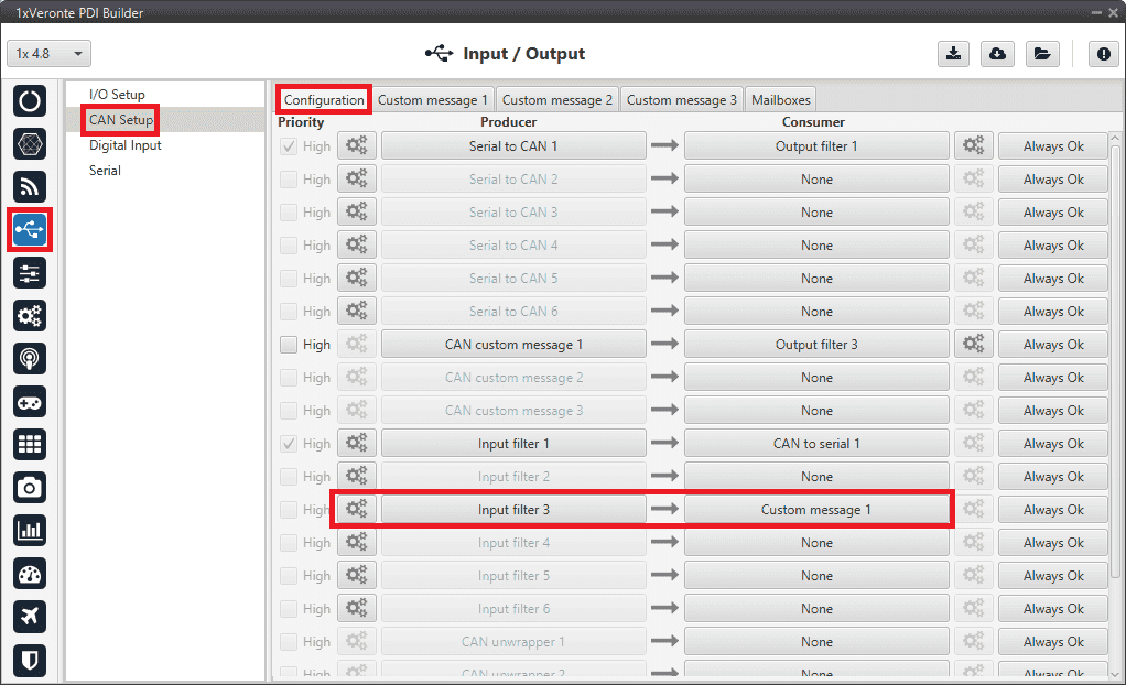
1x PDI Builder - CAN Setup configuration
Go to Input/Output menu \(\rightarrow\) CAN Setup panel \(\rightarrow\) Custom message 1 tab (since the input filter has been connected to the Custom message 1 consumer).
Users can configure the reception of MC110 variables and store them internally for other uses in the configuration.
To do this, add in RX fields the same messages that have been configured in the MC110 PDI Builder as TX Messages:
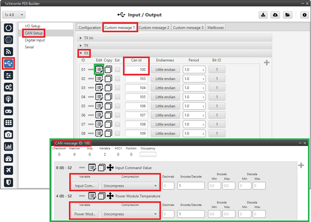
1x PDI Builder - Custom message 1 configuration
For more information on configuring CAN custom messages, refer to the Custom Messages types - Input/Output section of this manual.
Go to Input/Output menu \(\rightarrow\) CAN Setup panel \(\rightarrow\) Mailboxes tab.
Finally, configure the reception mailboxes.
In this case, CAN messages with ID 100 and with ID 103 to 109 (8 messages in total) are being sent, which in binary is: 0110 0100 and from 0110 0111 to 0110 1101.
Therefore, 8 mailboxes are configured with ID 01100100 and mask 1110000.
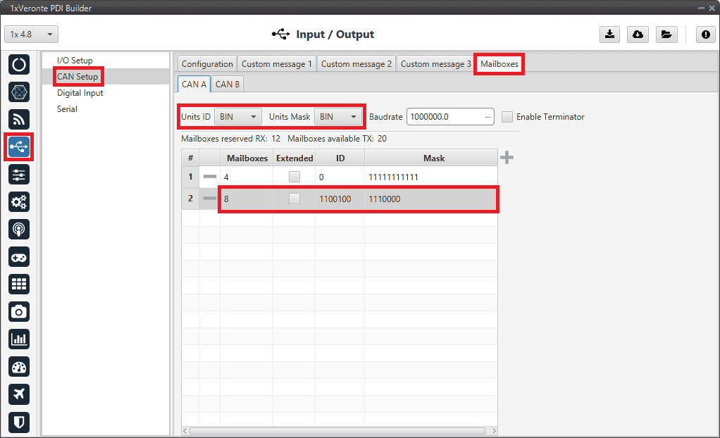
1x PDI Builder - Mailboxes configuration
For more information on mailboxes, see the Mailboxes (CAN Setup) - Input/Output section of this manual.
Veronte Gimbal
This section explains the configuration required to control and operate Veronte Gimbal 10z or Veronte Gimbal 30z.
On the one hand, the following diagram illustrates the communication required between a Veronte Autopilot 1x and the Veronte Gimbal to control its movements:
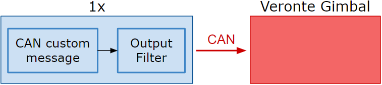
Communication diagram 1x \(\rightarrow\) Veronte Gimbal
On the other hand, to allow communication between Veronte Autopilot 1x and the video board integrated in the Veronte Gimbal camera the following connection is required:
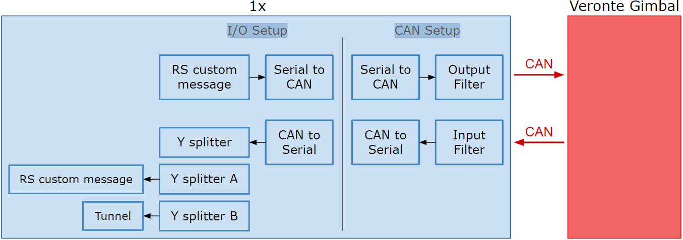
Communication diagram 1x \(\leftrightarrow\) Veronte Gimbal
In the 1x PDI Builder software there is already a template with the required configuration shown in the diagrams above. Users can access it in the following way:
Open 1x PDI Builder app.
Click ‘1xVeronte’ option.

Veronte Gimbal - 1xVeronte option
In the initial menu of the app, import a configuration from the repo clicking on
 .
.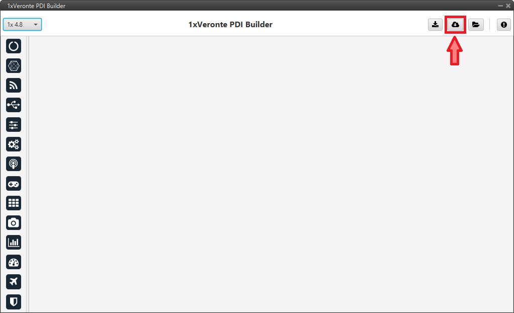
Veronte Gimbal - Import from repo
The following window will appear while the templates are being downloaded:
Veronte Gimbal - Downloading templates
In the templates menu, select the Veronte Gimbal configuration template and press Import to import it to the app.
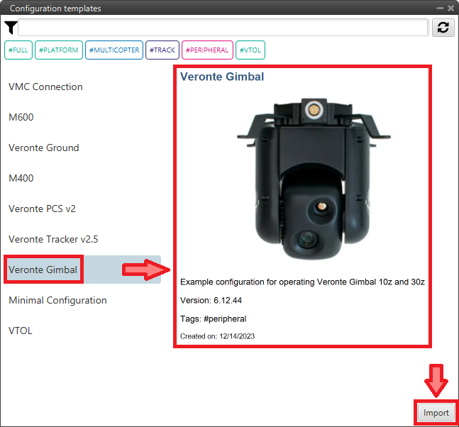
Veronte Gimbal - Veronte Gimbal configuration template
Now, users have to add the Veronte Gimbal control aspects of this configuration template to their own Autopilot 1x configuration.
Controlling Veronte Gimbal movement
Concerning the movement control of the Veronte Gimbal, these are the relevant parts of the configuration:
In the Input/Output menu \(\rightarrow\) CAN Setup panel \(\rightarrow\) Configuration tab.
A CAN custom message producer must be connected to an Output filter consumer. In this example, CAN custom message 1 is connected to Output filter 3 and CAN A bus has been chosen.
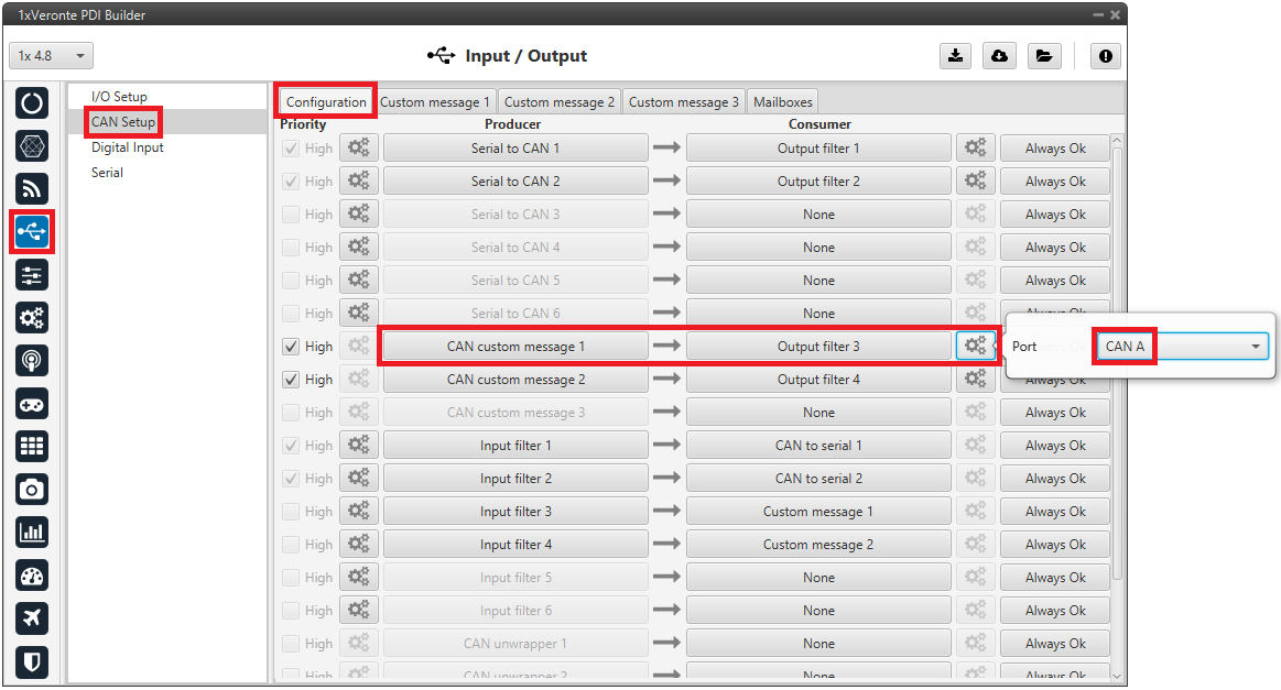
Veronte Gimbal - CAN Setup configuration panel
In the Input/Output menu \(\rightarrow\) CAN Setup panel \(\rightarrow\) Custom message 1 tab (since the producer CAN custom message 1 has been connected to the output filter).
The following parameters must be set for 2 CAN messages on TX (as they are for tranmission) with CAN ID 0 and 1. More information on the configuration of CAN messages can be found in the TX/TX Ini Messages (Custom Messages) - Input/Output section of this manual.
Warning
These specific CAN IDs are entered because they have to match the ones configured in the Gimbal, which are configured by default with these ids.
Can id: 0 / 1
Endianness: Little endian
Period: 0.01 s
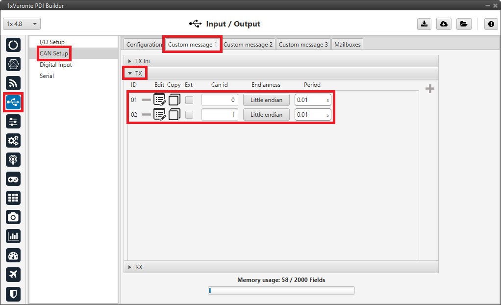
Veronte Gimbal - Custom message panel
Click on
 to access their configuration. This is almost the same for both messages but changing the variable:
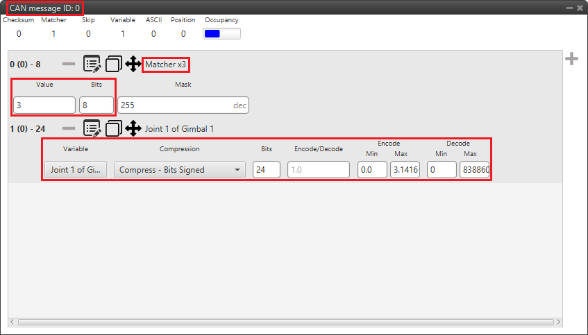
Veronte Gimbal - CAN custom message ID 0 configuration
Matcher
Value: 3
Bits: 8
Variable
Variable: Joint 1 of Gimbal 1
Compression: Compress - Bits Signed
Bits: 24
Encode - Min/Max: 0.0/3.1416
Decode - Min/Max: 0/8388608
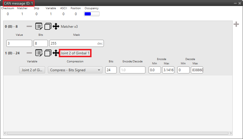
Veronte Gimbal - CAN custom message ID 1 configuration
Matcher
Value: 3
Bits: 8
Variable
Variable: Joint 2 of Gimbal 1
Compression: Compress - Bits Signed
Bits: 24
Encode - Min/Max: 0.0/3.1416
Decode - Min/Max: 0/8388608
Communication with Veronte Gimbal camera video board
The following are the configuration aspects of the communication with the gimbal camera video board.
CAN commands sent by Autopilot 1x
In the Input/Output menu \(\rightarrow\) I/O Setup panel.
A RS custom message producer is connected to a Serial to CAN consumer. In this example, RS custom message 1 is connected to Serial to CAN 2.
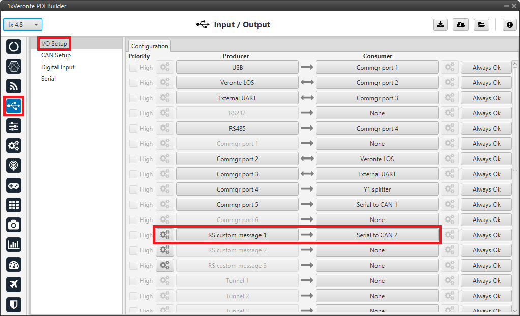
Veronte Gimbal - I/O Setup configuration panel
Click on
 to access the RS custom message configuration. It consists of 4 messages for request variables, i.e. they request information from the video board of the gimbal camera.
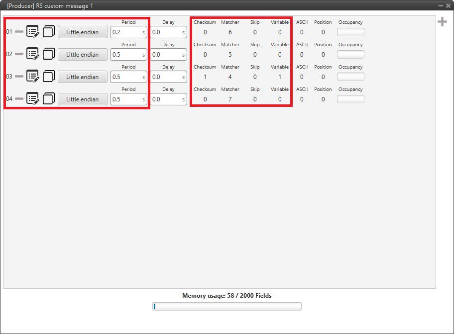
Veronte Gimbal - RS producer custom message configuration
Message
Endianness
Period
01
Little endian
0.2 s
02
Little endian
0.5 s
03
Little endian
0.5 s
04
Little endian
0.5 s
In the Input/Output menu \(\rightarrow\) CAN Setup panel \(\rightarrow\) Configuration tab.
A Serial to CAN producer with Id 1304 must be connected to an Output filter consumer. In this example, Serial to CAN 2 is connected to Output filter 2 and CAN A bus has been chosen.
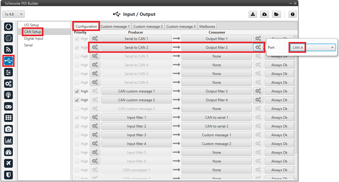
Veronte Gimbal - CAN Setup configuration panel
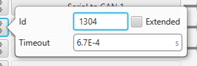
Veronte Gimbal - Serial to CAN configuration
CAN commands received on Autopilot 1x
In the Input/Output menu \(\rightarrow\) CAN Setup panel \(\rightarrow\) Configuration tab.
An Input filter producer with Id 1303 must be connected to a CAN to serial consumer. In this example, Input filter 2 configured to CAN A bus, is connected to CAN to serial 2.
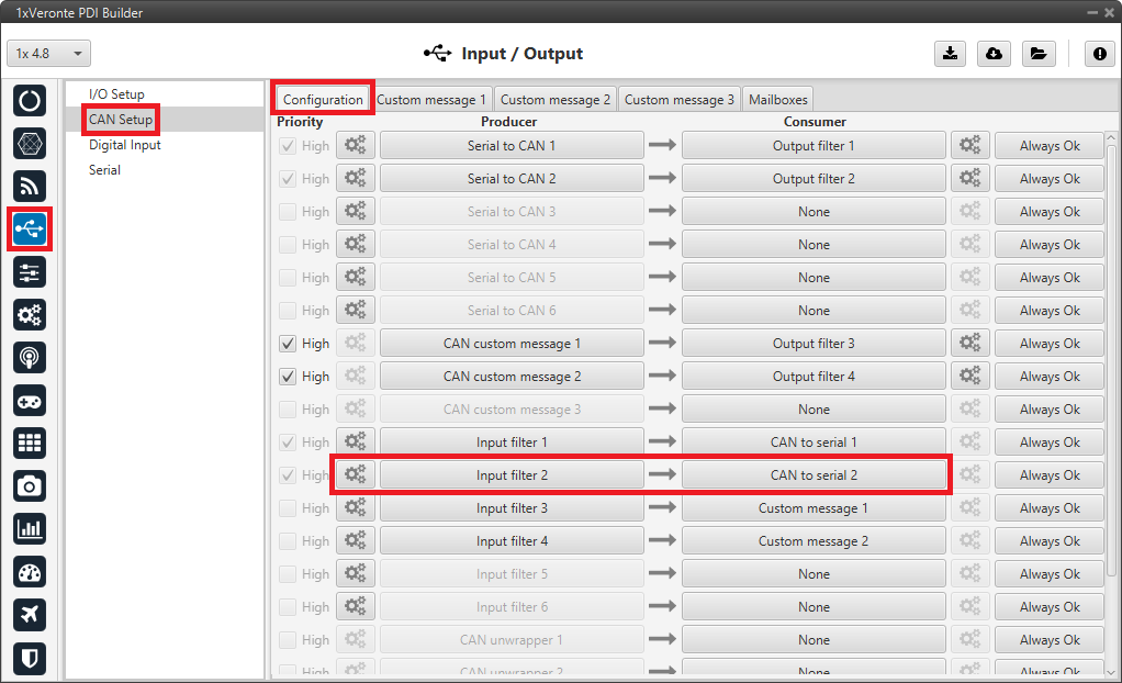
Veronte Gimbal - CAN Setup configuration panel
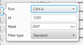
Veronte Gimbal - Input filter configuration
In the Input/Output menu \(\rightarrow\) CAN Setup panel \(\rightarrow\) Mailboxes tab.
20 reception mailboxes with ID 1303 are configured in CAN A bus (as the input filter has been configured to CAN A):
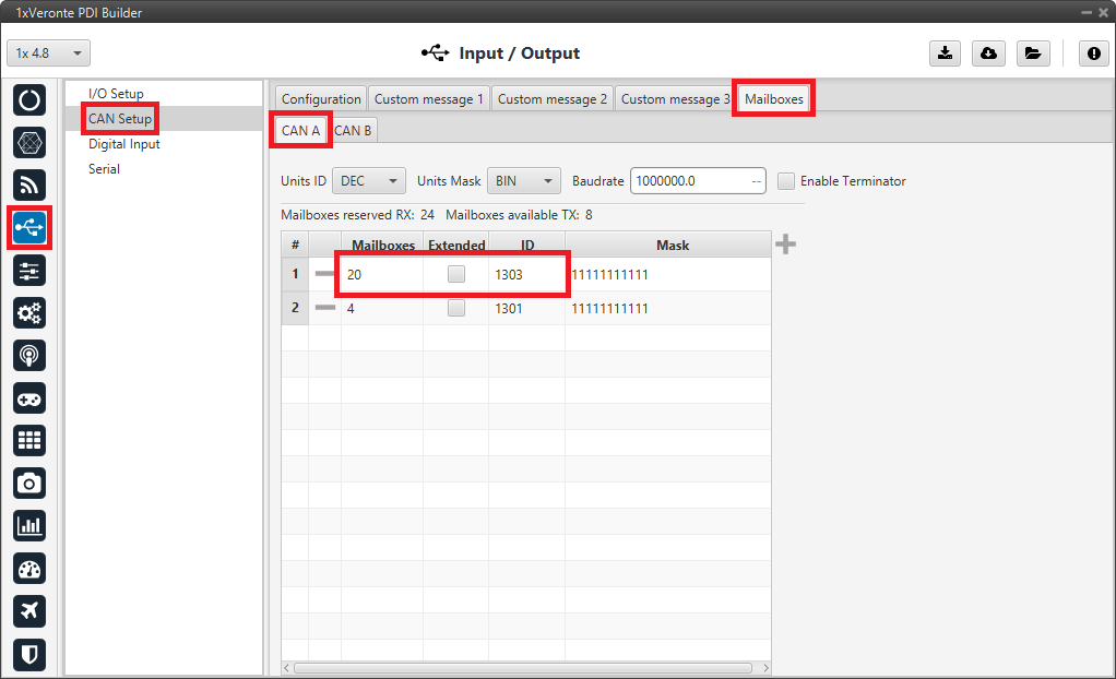
Veronte Gimbal - Mailboxes configuration
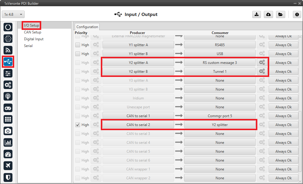
In the Input/Output menu \(\rightarrow\) I/O Setup panel.
A CAN to serial producer is connected to a Y splitter consumer. Then, a Y splitter A producer is connected to a RS custom message consumer and a Y splitter B producer is connected to a Tunnel consumer, configured to App 2 address.
This connection is made in order to read and process the information received from the video board (RS custom message consumer) while sending this information to Veronte Ops. So Autopilot 1x is acting as a tunnel between the video board and Veronte Ops.
In this example, CAN to serial 2 is connected to Y2 splitter, Y2 splitter A to RS custom message 3 and Y2 splitter B to Tunnel 1.
Veronte Gimbal - CAN Setup configuration panel
Click on
to access the RS custom message configuration. It consists of 4 messages to read the video board information from the gimbal camera that has been previously requested.Important
They must be configured as Little endian.
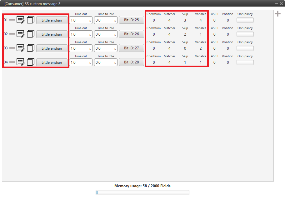
Veronte Gimbal - RS consumer custom message configuration
Finally, click on
to access the Tunnel configuration: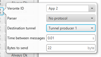
Veronte Gimbal - Tunnel configuration
Veronte ID: App 2
Parser: No protocol
Destination tunnel: Tunnel producer 1
Time between messages: 0.01 s
Bytes to send: 22 byte
Gimbal block program
Finally, in the Block Programs menu, a Gimbal program has also been created to allow a correct communication between Veronte Autopilot 1x and the video board integrated in the Veronte Gimbal camera.
Warning
Users must add it to their own configuration in exactly the same way.
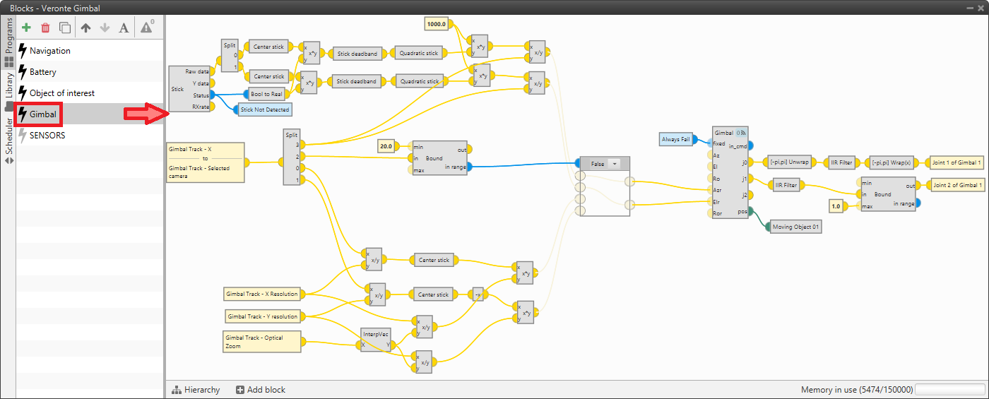
Veronte Gimbal - Block program
VSE (Veronte Stick Expander)
To configure the VSE in 1x PDI Builder it is only needed to follow the steps explained in the Ground unit configuration of the PPM Stick - General case integration example.
Important
In the step 1 of that explanation, there is already a transmitter configured with the required VSE configuration, users will find it as Brand: Embention and Model: Stick Expander.
The number of channels configured here must match those set in the VSE application. For more information on this, refer to the Channels section of the Stick Hardware Manual.
Furthermore, as the number of channels is modified, the Brand name will change to Customize.