Mission Setup
Introducction
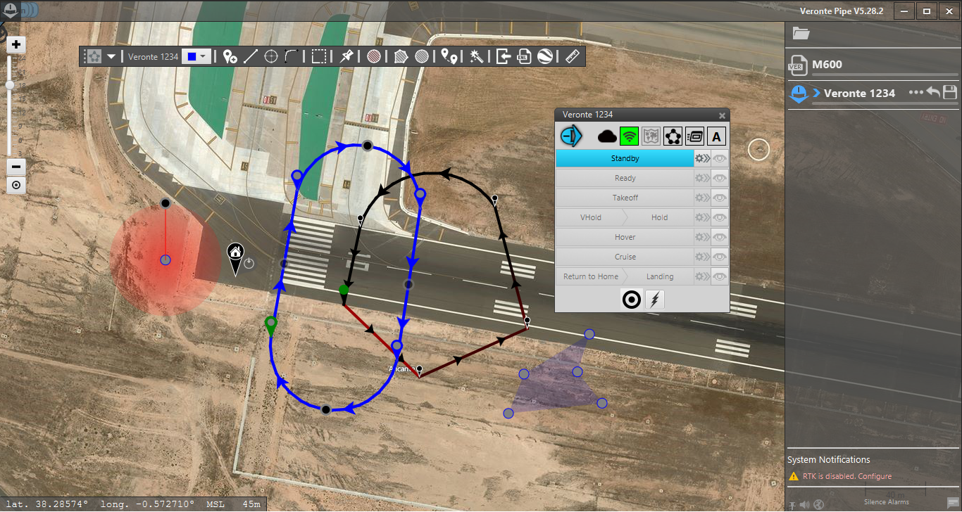
A mission can be configured using the Mission Menu. Firstly, Veronte Air has to be selected (it usually appears with the name of the UAV) because the Mission will be saved in the Air Autopilot. Then, using the graphical tool of this menu, the trajectory of the aircraft can be drawn, along with other elements to take into account during the mission such as polygons, obstacles or event markers.
Mission Setup
You can realice two or more missions simultaneously. The path created here will be directly linked to the Cruise guidance mode, so each time the aircraft is in a phase with cruise guidance, it will start to follow the track made in the mission menu.
Terrain profile and Magfield
Before to start the configuration of your mission, you have to set the terrain profile and the magnetic field. If you click in  you can access to this settings.
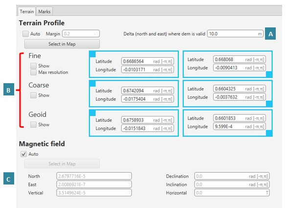
Terrain profile and magnetic field settings
A |
Delta parameter |
B |
Meshes of terrestrial mode |
C |
Magnetic vector |
Delta parameter: when you are flying, your aircraft measures the distance to the floor (AGL) through two or more systems: LIDAR, or another similar, and with the data of the meshes. During the flight it is possible that the position error is so large that the measure of the meshes can be wrong. So we define delta parameter to describe the radio of the circunference where we will use both systems, if the position error is bigger than the delta parameter we will use LIDAR alone.
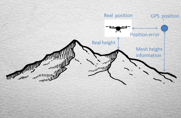
Delta Parameter
Meshes of terrestrial mode: we establish three different meshes (Fine, Coarse and Geoid), for each one we will introduce the coordenates of the upper left corner and the lower right corner or we can selec the zone in the map too.
Fine: Smaller mesh than the coarse one, but with detailed information about the altitude at more points.
Coarse: Big mesh with not much detail.
Geoide: Big mesh which provides the geoid height
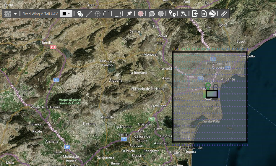
Fine and Coarse meshes
The meshes have fixed optimal start dimensions but they can be modified. Dimensions increasing means a lower zone definition so the tool must be changed if really necessary (the greater the resolution the smaller the mesh, because more resolution implies a heavier file to store that data).
If Auto is enabled the system will move automatically the meshes. In order to move them manually and save the updates is important to deselect the Auto tool. The system will display an error if there is not a configured mission on the map.
Margin is the percentage at which the system will recalculate the mission if the route is displaced. In other words, if the mission is displaced of the 60% of the area (Coarse or Fine) and the margin is set at 0.8 (the value can be set in percentage by changing the measurement unit) the mission will be not recalculated. If the mission is 81% (or more) away from the previous one the system will recalculate the mission. A low value (or zero) of Margin means more precision of the terrain profile but the system will recalculate more times (or each time) when the mission is modified.
Show option displays the mesh on the screen, allowing the user to move them in order to locate them over the mission area.
Magnetic vector: you can introduce or select in the map the magnetic vector of the zone. As far as the Magfield is concerned, the Auto check has to be marked to take the magnetic declination information of the mission area.
Warning
Before the flight, check that the meshes are over the mission area, especially if carrying out an operation in mountainous terrain.
Marks
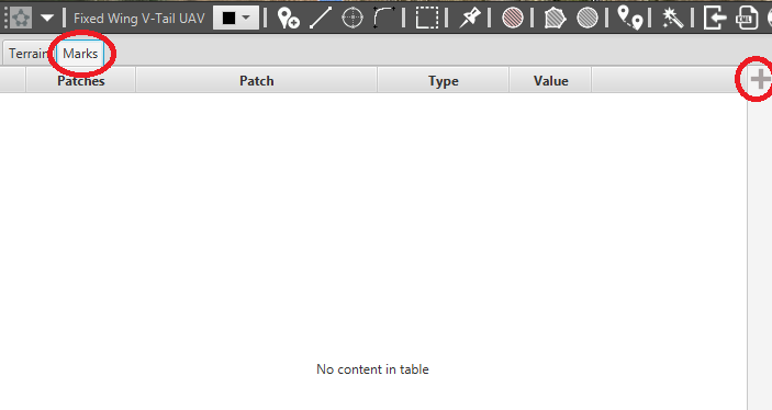
Marks menu
If you click in Marks flange you will access to this menu, and with “+” you can add new patches.

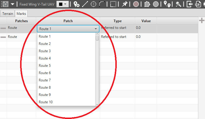
Guidance methods
Doing double click in Route you can select the guidance method that you want and with double click in Route n you will reference the patch to the Route n (for example), it is the same procedure for the other methods.
Guidance Method Number
Approach |
L0/A1/L2/A3/L4/L5 |
Climbing |
L4/A3/L2/A1 |
Route |
800 waypoints |
Taxi |
Taxi1/Taxi2 |
VTol |
VTol1/VTol2/VTol3 |
Rendezvous |
Rendezvous1/Rendezvous2/Rendezvous3 |
This channels are available for each guidance method.