Configuration
This section details a step by step explanation of how to configure SIL Simulator.
dll_config.vcfg file
This file sets the simulation configuration, and it is common for both simulation options: Veronte Console and Veronte S-Function for Simulink.
dll_config.vcfg file indicates the location of the Veronte DLL and Veronte image and establishes some parameters of the simulation, as the hardware version to simulate or the ID of the virtual autopilot.
This is an example of dll_config:

# Path to DLL
\dll .\x64\VeronteDLL.dll

# Path to image file  (absolute or relative to dll)
\image .\..\Veronte_SD_Image.img

# Hardware version
\hwversion 4.8

# Autopilot ID
\idversion 2
Before configuring SIL Simulator, these are aspects of the dll_config.vcfg file to consider for a proper functioning of the simulation:
Location of dll_config.vcfg file: It must be placed in the same path as the executable code to run. Depending on the simulation option to use, it must be placed in:
VeronteConsole.exepath if using Veronte Console.slxpath if using Veronte S-function for SimulinkNote
.slx files store Simulink model information in a reduced size. As previously explained, users must program their own Simulink workspace according to their aircraft and simulation goal, but an example is provided in the SIL folder (
mex_function_example.slx).
DLL and image files paths: It is crucial to precisely indicate the paths of DLL and image files.

Hardware version parameter
\hwversion version
Users can decide which hardware version to simulate:
4.0 |
hwversion 4.0 |
4.5 |
hwversion 4.5 |
4.8 |
hwversion 4.8 |
ID version parameter
\idversion index
Available Autopilot IDs vary depending on the selected hardware version. The index to be entered will be indicated by the following table:
|
0 |
1 |
2 |
3 |
4 |
5 |
|---|---|---|---|---|---|---|
|
1008 |
1025 |
1128 |
1373 |
1559 |
1654 |
|
1805 |
1862 |
1871 |
2375 |
2680 |
2821 |
|
4041 |
4064 |
4065 |
4144 |
4146 |
4213 |
Step by step - Veronte S-Function
Once decompressed, open the SIL folder.
SIL folder
Ensure that the
dll_config.vcfgfile is in the same path as the.slxfile.Note
.slx files store Simulink model information in a reduced size. As previously explained, users must program their own Simulink workspace according to their aircraft and simulation goal, but an example is provided in the SIL folder (
mex_function_example.slx).Configure the
dll_config.vcfgfile in the following cases:If the hardware version to simulate differs from v4.0.
If the DLL and image files are not located in the paths specified in
dll_config.vcfg.
Parameters to configure:
Path to DLL file
VeronteDLL.dll(absolute or relative to the.slxfile)Path to image file
Veronte_SD_Image.img(absolute or relative to DLL file)(Optional) Hardware version to simulate
(Optional and dependent on hardware version) Autopilot ID to simulate
Warning
Autopilot ID parameter only can be chosen if hardware version is also specified. For more information about setting the ID parameter, consult dll_config.vcfg file section of the present manual.
Open Simulink and configure the blocks explained below:
Add a S-function block, and point to
Veronte_SIL.mexw64code by editing the S-function name:
S-Function block parameters
Add a UDP serial communication block and connect it to USB data and length inputs of Veronte S-function.
Add a second UDP serial communication block and connect it to the USB outputs of Veronte S-function.

UDP Blocks
Configure the desired destination port.

Destination UDP Port
For extra information about Simulink configuration, consult the Simulink workspace section of this manual.
In Veronte Link application, configure a UDP connection with the following parameters:
Note
For more information about configurating connections, please consult Connection section of the Veronte Link user manual.
Type of connection: UDP
IP: IP previously configured in Simulink workspace
Port: Port previously configured in Simulink workspace
Run the simulation by running the Simulink model.
Check that the Autopilot 1x appears in Veronte Link as Connected and Ready:

Veronte Link
Note
The autopilot may appear as Loaded with errors in Veronte Link for reasons not related to the simulation configuration. Refer to Loaded with errors in Veronte Link - Troubleshooting section of this manual.
Once the simulation starts, user can proceed as with a physical autopilot:
1x PDI Builder for configuration.
Veronte Ops for operation and mission.
HIL Simulator for simulating the virtual autopilot with external simulators.
Important events or messages occuring within the simulation are registered on
SIL.log.
Step by step - Veronte Console
Once decompressed, open the SIL folder.
SIL folder
Ensure that the
dll_config.vcfgfile is in the same path asVeronteConsole.exe.Configure the
dll_config.vcfgfile in the following cases:If the hardware version to simulate differs from v4.0.
If the DLL and image files are not located in the paths specified in
dll_config.vcfg.
Parameters to configure:
Path to DLL file
VeronteDLL.dll(absolute or relative toVeronteConsole.exe)Path to image file
Veronte_SD_Image.img(absolute or relative to DLL file)(Optional) Hardware version to simulate
(Optional and dependent on hardware version) Autopilot ID to simulate
Warning
Autopilot ID parameter only can be chosen if hardware version is also specified. For more information about setting the ID parameter, consult dll_config.vcfg file section of the present manual.
In Veronte Link application, configure a UDP connection with the following parameters:
Note
For more information about configurating connections, please consult Connection section of the Veronte Link user manual.
Type of connection: UDP
IP: 127.0.0.1
Port: 12345
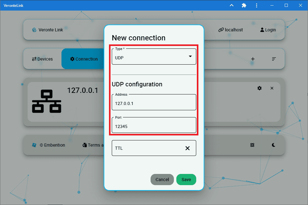
Veronte Link - UDP Connection for Veronte Console
Run the simulation by executing Veronte Console.exe.
Check that the Autopilot 1x appears in Veronte Link as Connected and Ready:
Veronte Link
Note
The autopilot may appear as Loaded with errors in Veronte Link for reasons not related to the simulation configuration. Refer to Loaded with errors in Veronte Link - Troubleshooting section of this manual.
Once the simulation starts, user can proceed as with a physical autopilot:
1x PDI Builder for configuration.
Veronte Ops for operation and mission.
HIL Simulator for simulating the virtual autopilot with external simulators.