CAN bus protocol
CAN message structure is defined by two main parts: cmd and data.
cmd (8 bits - 1 byte): First byte refers to the Message Type.
Messages Type are defined as follows:
Type
Value
Description
t_arbitration
0
Arbitration message
t_version
1
Version request / response
t_pwm_0_3_set
2
PWMs 0 to 3
t_pwm_4_7_set
3
PWMs 4 to 7
4
Reserved
t_esc_tm
5
Scorpion Tribunus ESC telemetry data
t_esc_tm2
6
Jeti ESC telemetry data
t_bec_tm1
7
Jeti BEC telemetry data 1
t_bec_tm2
8
Jeti BEC telemetry data 2
t_temp_tm
9
Jeti Temperature sensor telemetry data
t_mcu_cmd
10
Lift MCU battery command
t_pwm_8_11_set
11
PWMs 8 to 11
t_pwm_12_15_set
12
PWMs 12 to 15
t_pwm_16_19_set
13
PWMs 16 to 19
14
Reserved
15
Reserved
t_cmd_maint
16
Command to go to Maintenance Mode
t_stick_sel
17
Command for Stick selection
t_mcu_tm1
18
Lift MCU telemetry data 1
t_mcu_tm2
19
Lift MCU telemetry data 2
Note
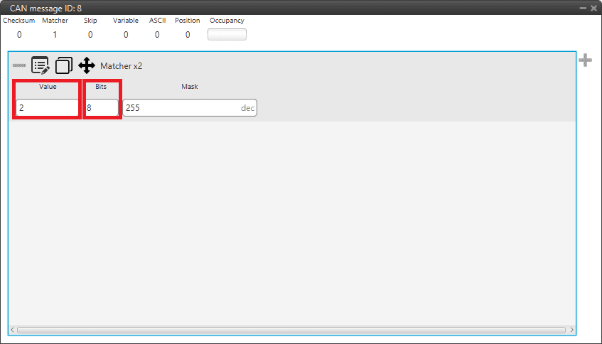
All these Message Type are defined as a “Matcher” in the CAN custom messages configuration. For example, for PWMs 0-3, the Message Type will be configured as follows:

Message Type example
Value: 2. This is because it is the value for the message for PWMs 0 to 3 (it is indifferent to the PWM number).
Bits: 8. This is because the Message Type is an 8-bit message.
data (up to 56 bits - 8 bytes): The following bytes refer to the Message data.
The following examples include complete messages, so each beginning corresponds to Message Type.
Arbitration messages
Status Message
Status message summarizes the status of all autopilots. This message is a producer in the 4x PDI Builder configuration, since it is created from the CAN messages of all three or four autopilots.
Byte |
Position |
Value |
Description |
|---|---|---|---|
0 |
0 - 7 |
0x00 |
Header |
1 |
0 - 7 |
0xFF |
Status message Header |
2 |
0 - 6 |
0 - 3 |
Selected AP (0 = AP1, 1 = AP2, 2 = AP3, 3 = External AP) |
7 |
0 - 1 |
Arbitration OFF/ON |
|
3 |
0 |
0 - 1 |
AP1 Alive |
1 |
0 - 1 |
AP2 Alive |
|
2 |
0 - 1 |
AP3 Alive |
|
3 |
0 - 1 |
External AP Alive |
|
4 |
0 - 1 |
AP1 Ready |
|
5 |
0 - 1 |
AP2 Ready |
|
6 |
0 - 1 |
AP3 Ready |
|
7 |
0 - 1 |
External AP Ready |
|
4 |
0 |
0 - 1 |
CBIT. System error. Will fail if any of the below items fail. |
1 |
0 - 1 |
PBIT. System Boot Ok. |
|
2 |
0 - 1 |
PDI Ok. Will fail if there is an error in configuration files. |
|
3 |
0 - 1 |
Memory Allocation OK |
|
4 |
0 - 1 |
CAN A Ok |
|
5 |
0 - 1 |
CAN B Ok |
|
6 |
0 - 1 |
CIO Low Task Ok |
|
7 |
0 - 1 |
CIO High Task Ok |
|
5 |
0 |
0 - 1 |
Power OK. All power indicators are OK. |
1 |
0 - 1 |
A Bus Voltage Ok |
|
2 |
0 - 1 |
B Bus Voltage Ok |
|
3 |
0 - 1 |
Arbiter Voltage Ok |
|
4 |
0 - 1 |
AP1 Voltage Ok |
|
5 |
0 - 1 |
AP2 Voltage Ok |
|
6 |
0 - 1 |
AP3 Voltage Ok |
|
7 |
0 - 1 |
Arbiter Mode. 1 = Normal, 0 = Maintenance |
Score Message
Score message contains the final score of an specific autopilot. This message is a producer in the 4x PDI Builder configuration, so it is created from the CAN messages of all three or four autopilots.
Byte |
Position |
Value |
Description |
|---|---|---|---|
0 |
0 - 7 |
0x00 |
Header |
1 |
0 - 7 |
0 - 3 |
Autopilot ID (0 = AP1, 1 = AP2, 2 = AP3, 3 = External AP) |
2 - 5 |
0 - 31 |
0 - 0xFFFF FFFF |
Autopilot Arbitration Score |
Ready Message
Ready message is sent from Autopilot 1x to Arbiter. It tells whether an Autopilot 1x is ready to fly or not. It is as consumer in the 4x PDI Builder configuration, so it is stored in memory.
Byte |
Position |
Value |
Description |
|---|---|---|---|
0 |
0 - 7 |
0x00 |
Header |
1 |
0 - 7 |
0xFF |
Ready Message Header |
2 |
0 (1 bit) |
0 - 1 |
Ready/Not Ready |
Arbitration Message
Arbitration message tells the arbitration value of a specific variable. It is as consumer in the 4x PDI Builder configuration, since it is stored in memory.
Byte |
Position |
Value |
Description |
|---|---|---|---|
0 |
0 - 7 |
0x00 |
Header |
1 |
0 - 7 |
0 - 31 |
Arbitration Variable Number |
2 - 5 |
0 - 31 |
0 - 0xFFFF FFFF |
Arbitration Variable Value |
