Altimeters
Lidar
The integration between Veronte Autopilot 1x and a lidar is performed using a variety of interfaces depending on the lidar device. The most common interfaces are I2C or analog although serial or CAN bus can also be used if the lidar is compatible.
Lidar Garmin Lite v3
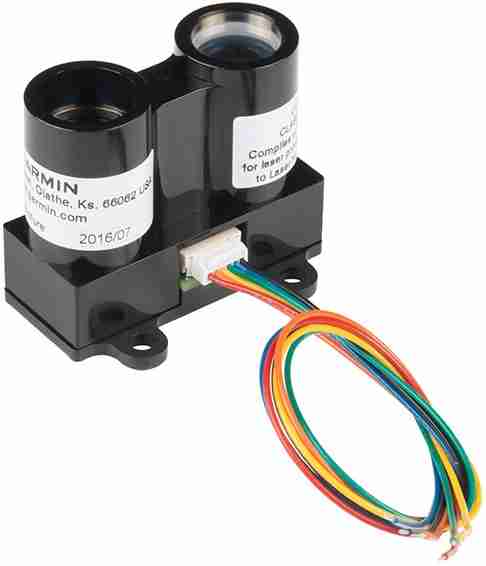
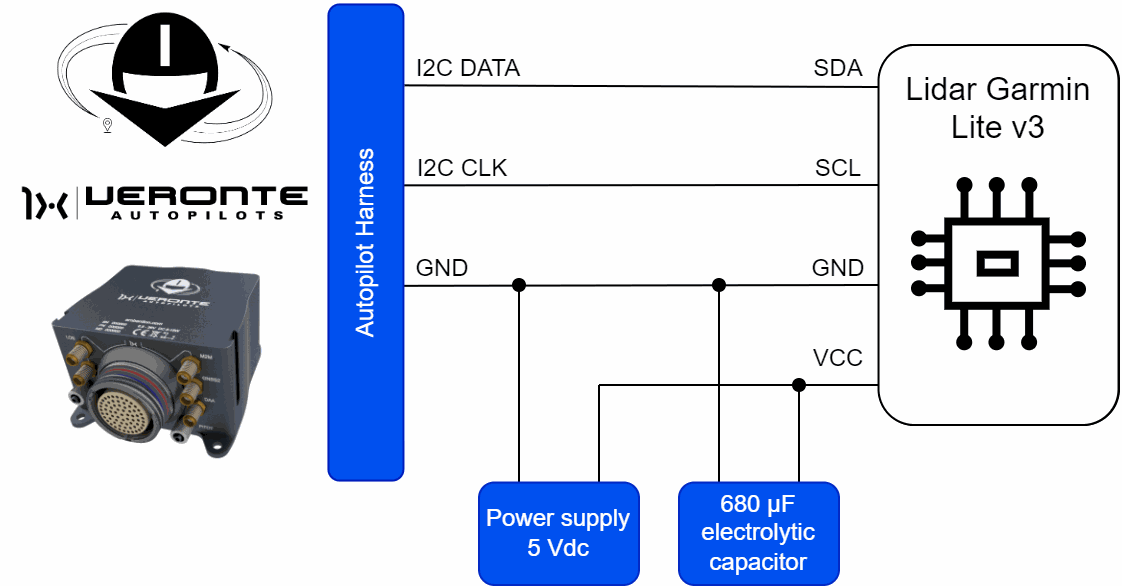
Lidar Garmin Lite v3 sensor integrates with Autopilot 1x via I2C connection.
Important
To ensure correct operation of the device, it is recommended to use an external power supply and not to connect it to the 3.3-5 V lines of Autopilot 1x.
Please note that it shares signal ground with Autopilot 1x.
| Autopilot 1x Harness | Lidar Garmin Lite v3 Connector | ||||
|---|---|---|---|---|---|
| PIN | Signal | Color Code | PIN | Signal | Color Code |
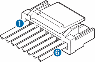
| 31 | I2C_CLK | White | 4 | I2C SCL | Green |
| 32 | I2C_DATA | Brown | 5 | I2C SDA | Blue |
| 35 | GND | Gray | 6 | Ground (-) | Black |
Warning
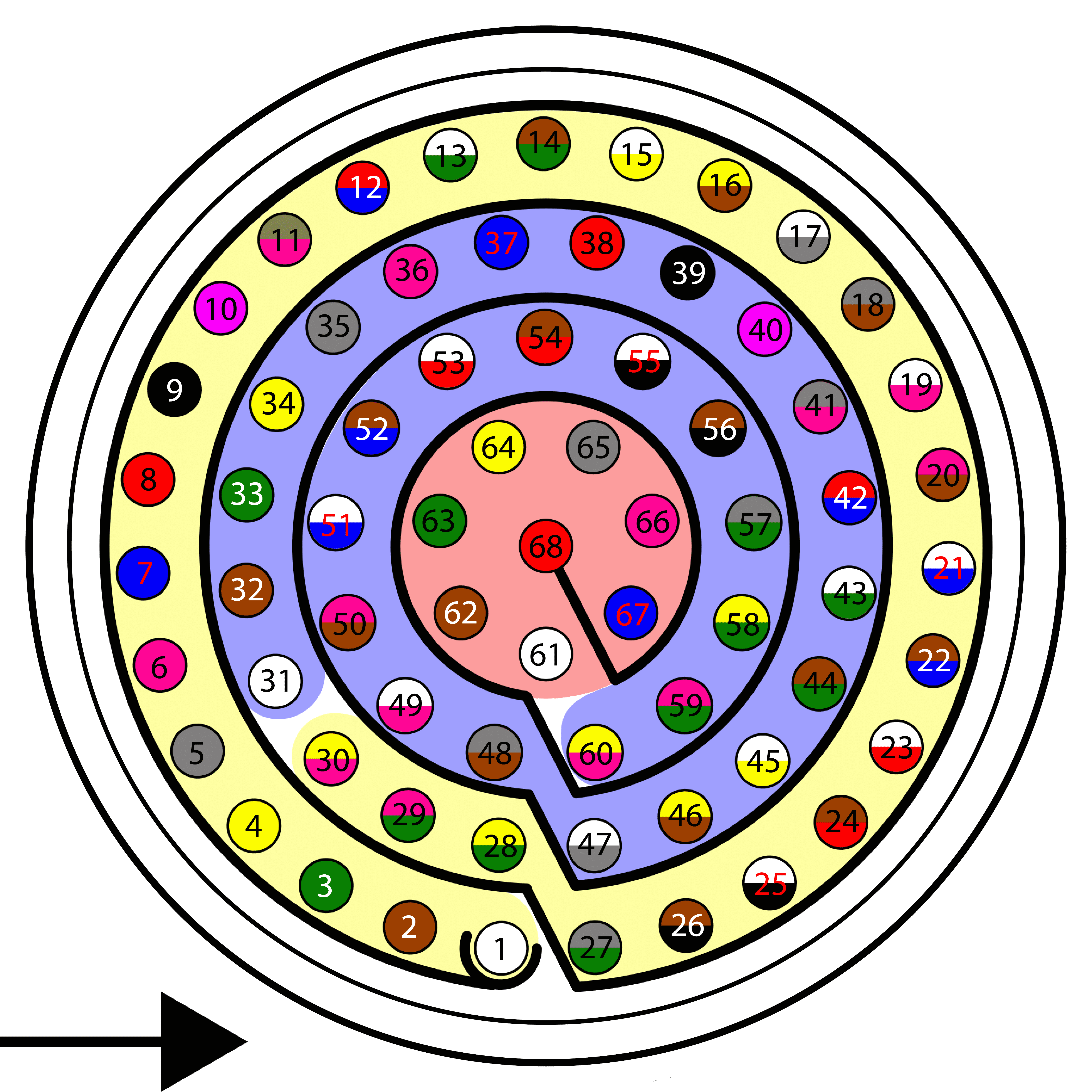
Remember!! In Autopilot 1x, all GND pins are common. Note that pin 54 is not a common GND pin.
Once the lidar is connected, the user must proceed to its software integration with Veronte Autopilot 1x by referring to the Lidar Garmin Lite v3 - Integration examples section of the 1x PDI Builder user manual.
Lightware LW20 Lidar

Lightware LW20 Lidar sensor integrates with Autopilot 1x via I2C connection.

Important
To ensure correct operation of the device, it is recommended to use an external power supply and not to connect it to the 3.3-5 V lines of Autopilot 1x.
Please note that it shares signal ground with Autopilot 1x.
| Autopilot 1x Harness | Lightware LW20 Lidar | ||||
|---|---|---|---|---|---|
| PIN | Signal | Color Code | PIN | Signal | Color Code |
| 31 | I2C_CLK | White | 2 | SCL | White |
| 32 | I2C_DATA | Brown | 1 | SDA | Yellow |
| 35 | GND | Gray | 8 | GND | Black |
Warning
Remember!! In Autopilot 1x, all GND pins are common. Note that pin 54 is not a common GND pin.
Once Lightware LW20 Lidar is connected, the user must proceed to its software installation with Veronte Autopilot 1x by referring to the Lightware LW20 Lidar - Integration examples section of the 1x PDI Builder user manual.
Lightware SF20 Lidar
Lightware SF20 Lidar sensor integrates with Autopilot 1x via I2C connection.
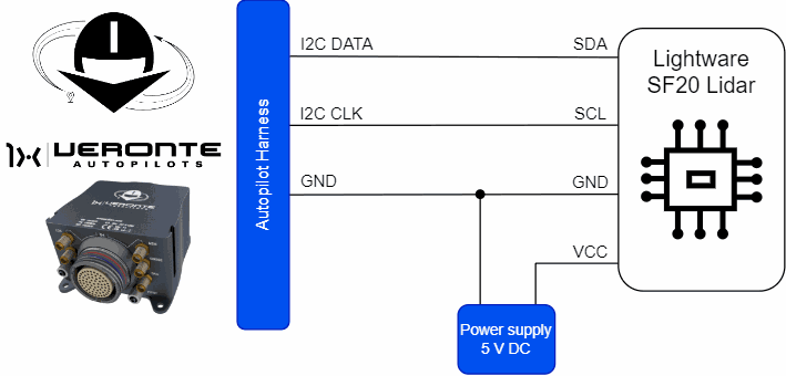
Important
To ensure correct operation of the device, it is recommended to use an external power supply and not to connect it to the 3.3-5 V lines of Autopilot 1x.
Please note that it shares signal ground with Autopilot 1x.
| Autopilot 1x Harness | Lightware SF20 Lidar | ||||
|---|---|---|---|---|---|
| PIN | Signal | Color Code | PIN | Signal | Color Code |
| 31 | I2C_CLK | White | 2 | SCL | White |
| 32 | I2C_DATA | Brown | 1 | SDA | Yellow |
| 35 | GND | Gray | 8 | GND | Black |
Warning
Remember!! In Autopilot 1x, all GND pins are common. Note that pin 54 is not a common GND pin.
Once Lightware SF20 Lidar is connected, the user must proceed to its software installation with Veronte Autopilot 1x. Since this setup is the same as for the Lightware LW20, please refer to the Lightware LW20 Lidar - Integration examples section of the 1x PDI Builder user manual.
Radar
Radar altimeters are common devices on aircrafts.
Ainstein CAN Radar
Ainstein CAN Radar sensor integrates with Autopilot 1x via CAN connection.
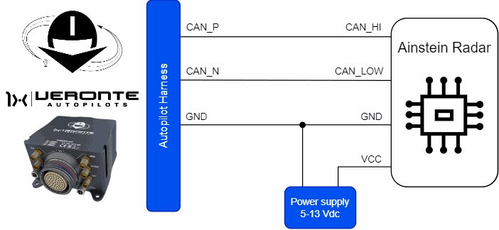
Important
To ensure correct operation of the device, it is recommended to use an external power supply and not to connect it to the 5 V line of Autopilot 1x.
Please note that it shares signal ground with Autopilot 1x.
| Autopilot 1x Harness | Ainstein CAN Radar | ||||
|---|---|---|---|---|---|
| PIN | Signal | Color Code | PIN | Signal | Color Code |
| 25 | CANA_P | White-Black | 2 | CAN_HI | Green |
| 28 | CANB_P | Yellow-Green | |||
| 26 | CANA_N | Brown-Black | 3 | CAN_LOW | White |
| 29 | CANB_N | Pink-Green | |||
| 30 | GND | Yellow-Pink | 4 | Ground | Black |
Note
CAN A and CAN B buses are equivalent and can be used interchangeably for the integration of this device.
For more information on CAN connection, please visit CAN - Wiring connection section of this manual.
Warning
Remember!! In Autopilot 1x, all GND pins are common. Note that pin 54 is not a common GND pin.
Once Ainstein CAN Radar is connected, the user must proceed to its software installation with Veronte Autopilot 1x by referring to the Ainstein CAN Radar - Integration examples section of the 1x PDI Builder user manual.
© 2025 Embention. All rights reserved.