Air Data Sensors
High Speed Pitot Sensor
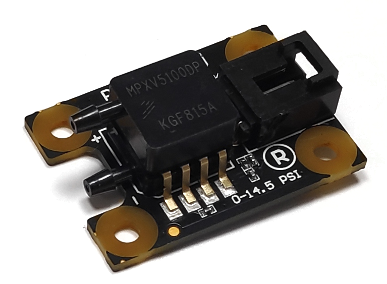
This section explains how to install the High Speed Pitot Sensor with an Autopilot 1x and configure it, so 1x measures the air speed from the electrical signals of High Speed Pitot Sensor.
Required Material
- Veronte Autopilot 1x with hardware version 4.8.
- High Speed Pitot Sensor.
- Veronte Harness CS for 1x v4.8 with Embention reference P001114.
- Power supply for 1x (6.5 - 36 V DC).
- Power supply for High Speed Pitot Sensor (5 V DC).
- Pneumatic tubing, with 3 mm of outer diameter and 1 mm of inner. Silicone material is recommended.
- Two T-connectors for the tubing.
Warning
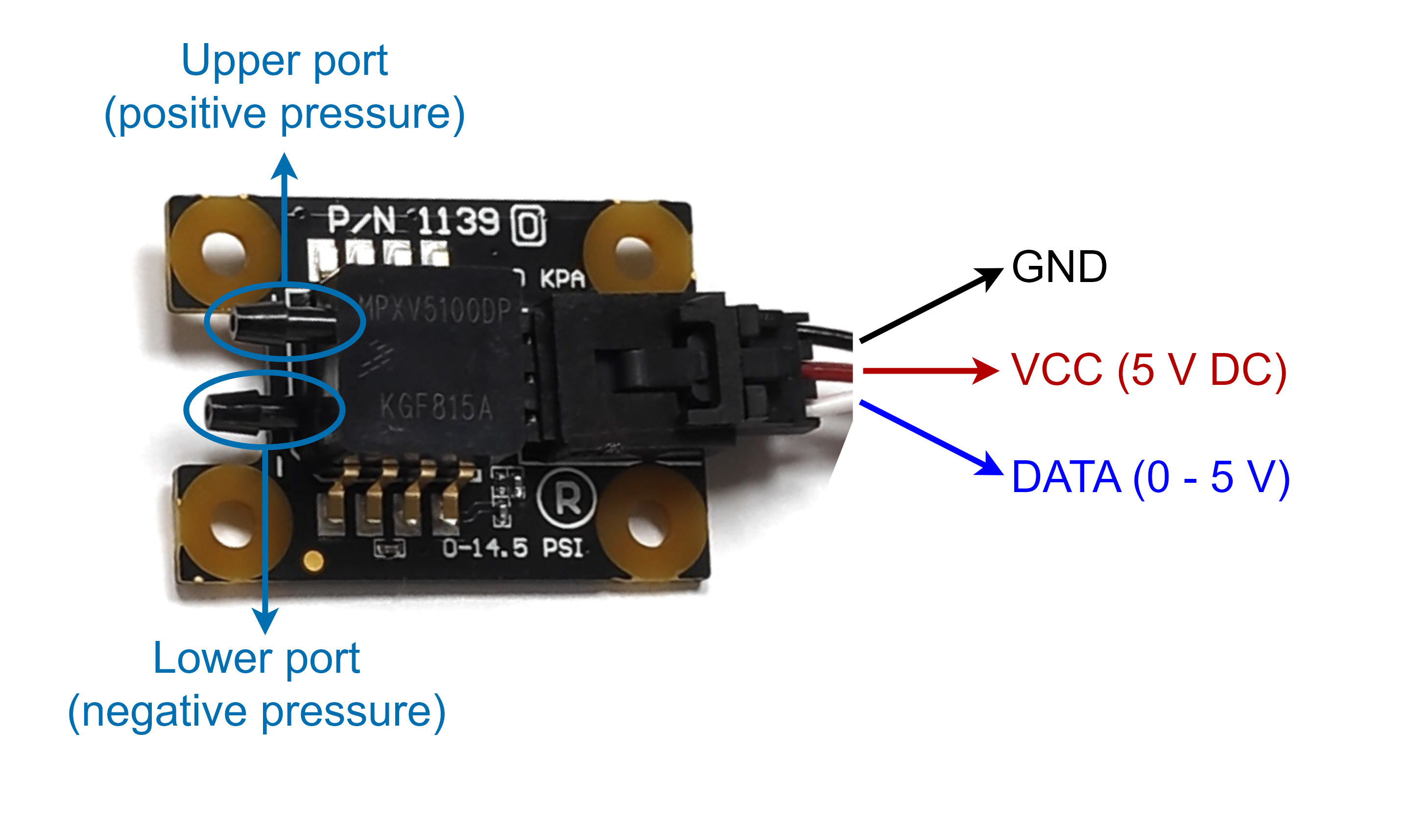
Take caution when connecting the pressure ports. This sensor only measures a positive pressure differential, so the sensor might be damaged if it reverse connected.
Ensure that the upper port is always at an equal or higher pressure than the lower port.
Connect the pneumatic tubes and wires according to the following diagrams:
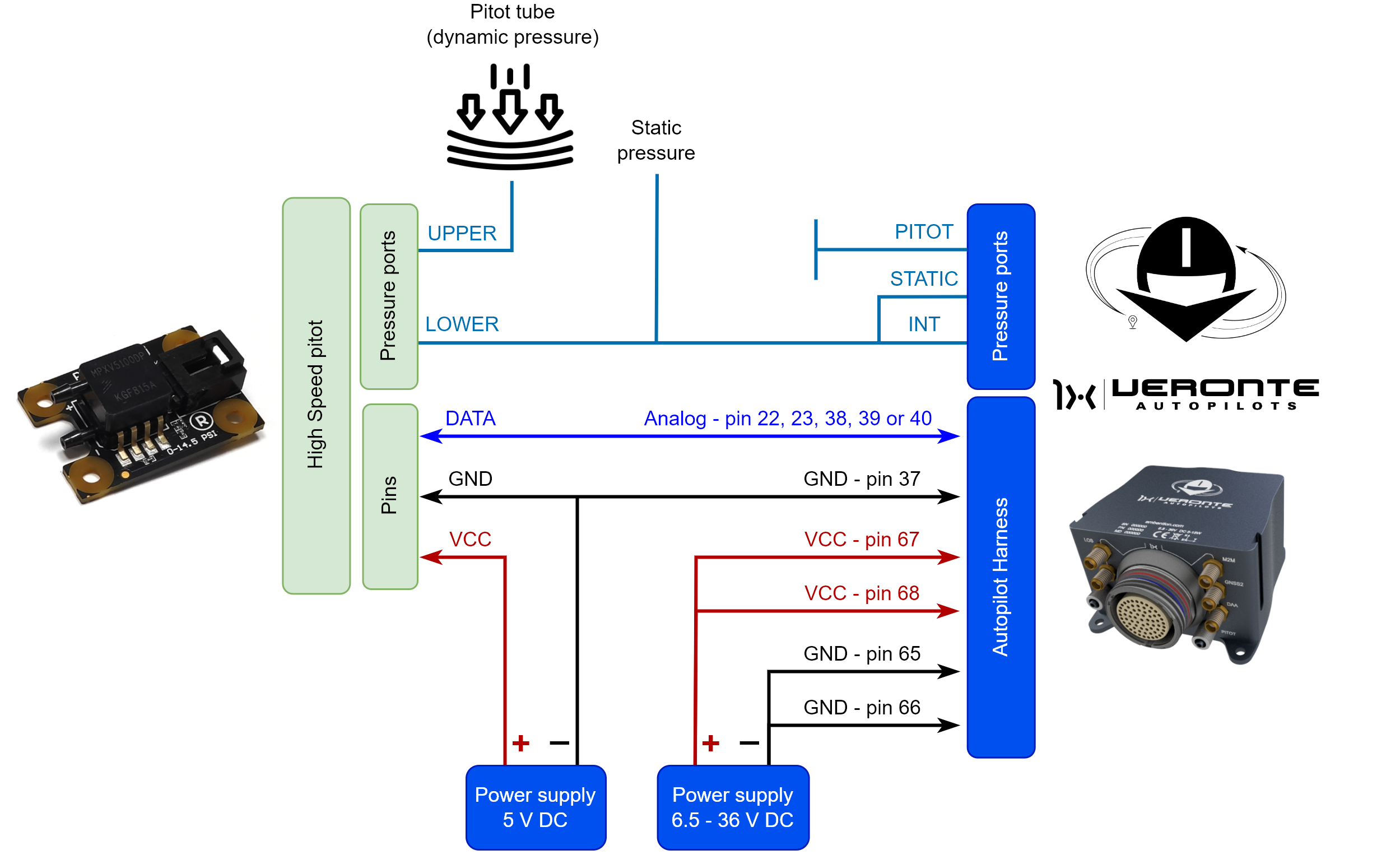
The analog pin defines which analog variable is used for configuration.
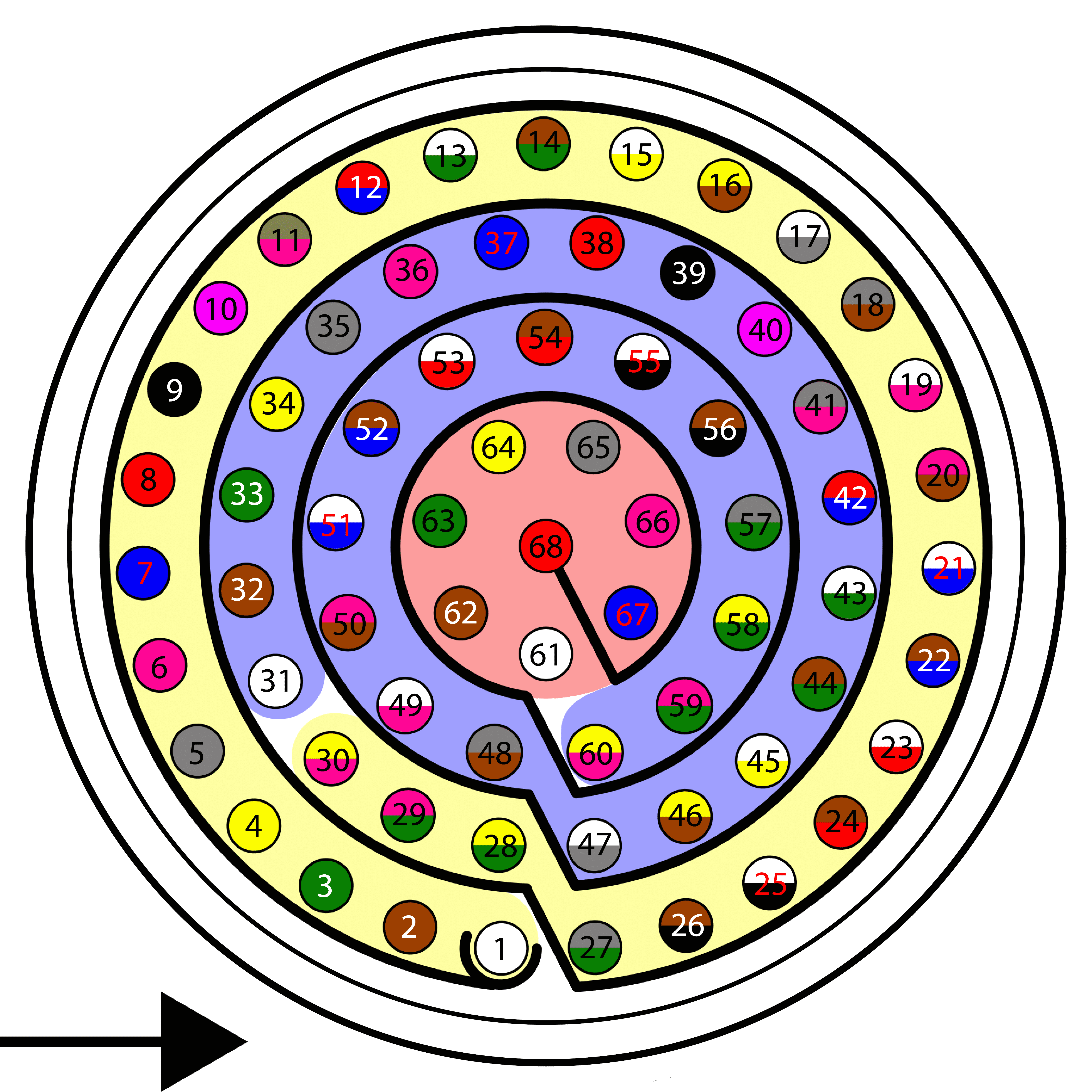
| Autopilot 1x Harness | High Speed Pitot Sensor | |||
|---|---|---|---|---|
| PIN | Signal | Color Code | Signal | Color Code |
| 38 | ANALOG_0 | Red | DATA | White |
| 39 | ANALOG_1 | Black | ||
| 40 | ANALOG_2 | Pink | ||
| 22 | ANALOG_3 | Brown - Blue | ||
| 23 | ANALOG_4 | White - Red | ||
| 37 | GND | Blue | GND | Black |
Warning
Remember!! In Autopilot 1x, all GND pins are common. Note that pin 54 is not a common GND pin.
Once the High Speed Pitot Sensor is connected, air speed measurements can be monitored with 1x PDI Builder using the variables ADC0 to ADC4. The integration of this device with Autopilot 1x as far as the software is concerned is explained in the High Speed Pitot Sensor - Integration examples section of 1x PDI Builder user manual.
OAT sensor 428 of MGL Avionics
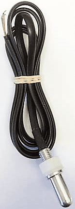
The OAT sensor 428 of MGL Avionics is an analogical temperature sensor that measures temperatures from -55°C to 150°C. It changes the voltage according to the temperature measured and therefore the connection to the autopilot is performed using the ADC pins.
The following resistors and wiring are necessary to connect an OAT sensor 428 to the Autopilot 1x:
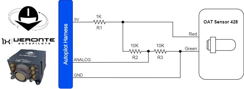
| Autopilot 1x Harness | ||
|---|---|---|
| PIN | Signal | Color Code |
| 36 | 5V | Pink |
| 37 | GND | Blue |
| 38 | ANALOG_0 | Red |
| 39 | ANALOG_1 | Black |
| 40 | ANALOG_2 | Pink |
| 22 | ANALOG_3 | Brown - Blue |
| 23 | ANALOG_4 | White - Red |
Warning
Remember!! In Autopilot 1x, all GND pins are common. Note that pin 54 is not a common GND pin.
Once connected the OAT sensor, the temperature can be monitored with 1x PDI Builder using the variables ADC0 to ADC4.
The integration of this device with Autopilot 1x is explained in the OAT Sensor - Integration examples section of the 1x PDI Builder user manual.
© 2026 Embention. All rights reserved.