Actuators/Servos
The user can configure any actuator compatible with the communication interfaces.
CAN
Pegasus PA-R-135-4
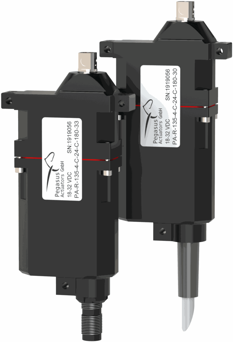
Pegasus PA-R-135-4 micro-low-profile servo is currently the world's smallest professional servo-actuator of its class.
The setup to be performed by the user should be as follows:

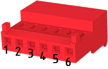
| Autopilot 1x Harness | Pegasus PA-R-135-4 Tyco MTA100 Connector |
||||
|---|---|---|---|---|---|
| PIN | Signal | Color Code | PIN | Signal | |
| 25 | CANA_P | White-Black | 3 | CANH | |
| 28 | CANB_P | Yellow-Green | |||
| 26 | CANA_N | Brown-Black | 1 | CANL | |
| 29 | CANB_N | Pink-Green | |||
| 30 | GND | Yellow-Pink | 6 | GND | |
Note
CAN A and CAN B buses are equivalent and can be used interchangeably for the integration of this device.
For more information on CAN connection, please visit CAN - Wiring connection section of this manual.
Warning
Remember!! In Autopilot 1x, all GND pins are common. Note that pin 54 is not a common GND pin.
Once the hardware integration of the device has been completed, it will be necessary to proceed with the software integration. To do this, follow the steps detailed in the Pegasus - Integration examples section of the 1x PDI Builder user manual.
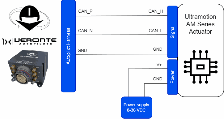
Ultra Motion
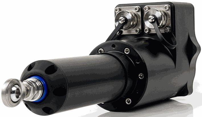
Ultra Motion servo is a high-precision actuator designed for demanding applications, with BLDC electronic control and non-contact absolute position feedback.
This device can be integrated with Autopilot 1x via CAN 2.0B protocol to ensure robust and efficient communication in the system.
The setup to be performed by the user should be as follows:
| Autopilot 1x Harness | Ultra Motion Signal Connector | ||||
|---|---|---|---|---|---|
| PIN | Signal | Color Code | PIN | Signal | Color Code |
| 25 | CANA_P | White-Black | 7 | CAN_H | Red |
| 28 | CANB_P | Yellow-Green | |||
| 26 | CANA_N | Brown-Black | 9 | CAN_L | White |
| 29 | CANB_N | Pink-Green | |||
| 30 | GND | Yellow-Pink | 8 | GND | Black |
Note
CAN A and CAN B buses are equivalent and can be used interchangeably for the integration of this device.
For more information on CAN connection, please visit CAN - Wiring connection section of this manual.
Warning
Remember!! In Autopilot 1x, all GND pins are common. Note that pin 54 is not a common GND pin.
Once the hardware installation has been completed, the user can find the explanataion for the software installation in the Ultra Motion - Integration examples section of the 1x PDI Builder user manual.
PWM
This section details the process of integrating a PWM servomotor with Autopilot 1x.
The connection diagram between the two devices should look like this:
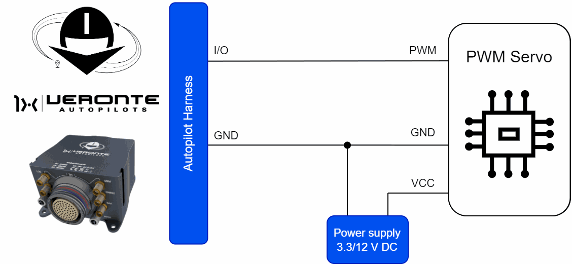
Important
Note that this servo must be connected to an external power supply, sharing signal ground with Autopilot 1x.
The PWM servo must be connected to one of the available I/O pins of Autopilot 1x.
| Autopilot 1x Harness | ||
|---|---|---|
| PIN | Signal | Color Code |
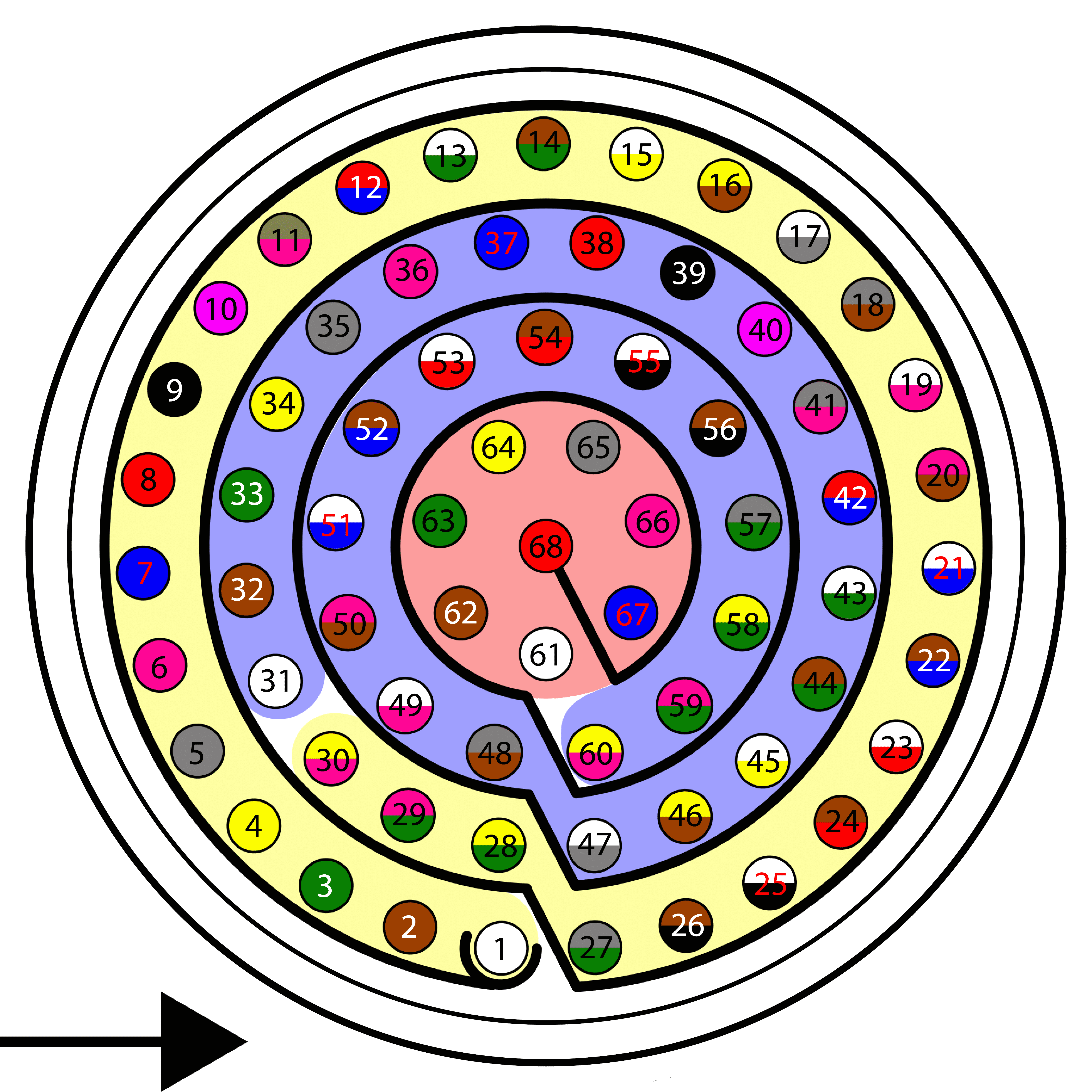
| 1 | I/O0 | White |
| 2 | I/O1 | Brown |
| 3 | I/O2 | Green |
| 4 | I/O3 | Yellow |
| 5 | I/O4 | Gray |
| 6 | I/O5 | Pink |
| 7 | I/O6 | Blue |
| 8 | I/O7 | Red |
| 9 | GND | Black |
| 10 | I/O8 | Violet |
| 11 | I/O9 | Gray-Pink |
| 12 | I/O10 | Red-Blue |
| 13 | I/O11 | White-Green |
| 14 | I/O12 | Brown-Green |
| 15 | I/O13 | White-Yellow |
| 16 | I/O14 | Yellow-Brown |
| 17 | I/O15 | White-Gray |
Warning
Remember!! In Autopilot 1x, all GND pins are common. Note that pin 54 is not a common GND pin.
Once the hardware connection is made, it is necessary to configure the I/O pin used. Since these I/O pins are preconfigured as GPIO, they must be set as PWM.
To do so, refer to and follow the steps described in the PWM - Integration examples section of the 1x PDI Builder user manual.
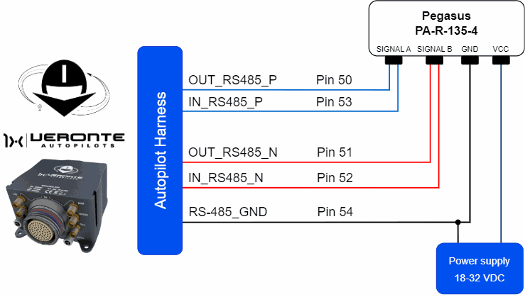
Serial
Pegasus PA-R-135-4
Pegasus PA-R-135-4 micro-low-profile servo is currently the world's smallest professional servo-actuator of its class.
The setup to be performed by the user should be as follows:
| Autopilot 1x Harness | Pegasus PA-R-135-4 Tyco MTA100 Connector |
||||
|---|---|---|---|---|---|
| PIN | Signal | Color Code | PIN | Signal | |
| 50 | OUT_RS485_P | Pink-Brown | 3 | SINGAL A | |
| 53 | IN_RS485_P | White-Red | |||
| 51 | OUT_RS485_N | White-Blue | 1 | SIGNAL B | |
| 52 | IN_RS485_N | Brown-Blue | |||
| 54 | OUT_GND | Brown-Red | 6 | GND | |
Once the hardware integration of the device has been completed, it will be necessary to proceed with the software integration. To do this, follow the steps detailed in the Pegasus - Integration examples section of the 1x PDI Builder user manual.
Volz DA26 - RS485
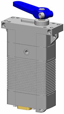
The following wiring connection is recommended for a RS485 half-duplex connection between Volz DA26 servos and Veronte Autopilot 1x:
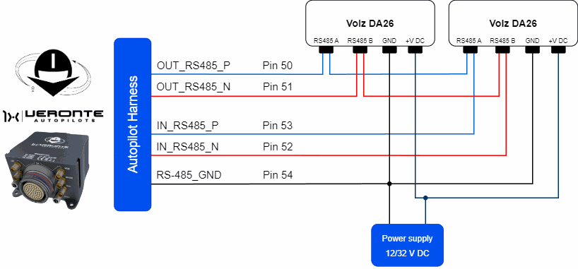
The above diagram is made for the case where 2 Volz DA26 servos are connected, however, the connection is the same in case the user wants to connect only one or as many servos as the bus allows.
Important
Note that this servo must be connected to an external power supply, sharing signal ground with Autopilot 1x.
| Autopilot 1x Harness | Volz DA26 Connector | |||
|---|---|---|---|---|
| PIN | Signal | Color Code | PIN | Signal |
| 50 | OUT_RS485_P | Pink-Brown | 1 | RS 485 A (Non-inverting Input/Output) |
| 53 | IN_RS485_P | White-Red | ||
| 51 | OUT_RS485_N | White-Blue | 2 | RS 485 B (Inverting Input/Output) |
| 52 | IN_RS485_N | Brown-Blue | ||
| 54 | OUT_GND | Brown-Red | 7 | GND (1) |
| 8 | GND (2) | |||
Warning
Note that this pin 54 is not a common GND pin.
Note
If users encounter any problems during wiring, please check the Half-duplex servo does not respond - Troubleshooting section of this manual.
Once the hardware integration of the device has been completed, it will be necessary to proceed with the software integration. To do this, follow the steps detailed in the Volz DA26-RS485 - Integration examples section of the 1x PDI Builder user manual.
© 2025 Embention. All rights reserved.