Technical
Features
-
Buses
- 1 x Ethernet port
- 1 x UART
- 1 x UART SuC/FTS
- 1 x CAN FD bus
- 2 x CAN 2.0 bus
- 2 x RS-232
- 2 x RS-485 full duplex bus
- 1 x I2C bus
- Over ethernet, RS-485 or RS-232 firmware update
- 1x BLOS module
-
Input / Output
- 8 x configurable input / output signals (5V)
- 2 x analog input signals 0 - 36 V
- 3 x analog input signals 0 - 5 V
- 1x EQUEP/4x ECAP (5V)
-
Power
- 2 x Redundant input power supply (8 - 54 V DC)
- 1 x output power with 3.3 V, up to 100 mA
- 1 x output power with 5 V, up to 100 mA
-
Protection
- EMI shield
- Against reverse polarity
- Against inrush current during power up
- Enhanced signal control on startup
- Enhanced power input redundancy
Note
The number of communication ports and signals can be increased with Veronte CEX or Veronte MEX.
Variants
Veronte Autopilot 1x has 2 variants:
- With Remote ID
- With ADS-B
ADS-B module
| Frequency band | 1090 MHz |
| Current consumption | Averaged 140 mA |
| Sensitivity | -80 dBm |
| RF output power | Configurable +30 dBm (1W), +27 dBm (0.5W), +24 dBm (0.25W) |
| ESD protection | All lines protected |
| MAVLink (baud) | 115200 bps |
| AERO (baud) | 115200 bps (AT commands) |
RemoteID module
| Frequency | WiFi & Bluetooth bands |
| Developed according to | RIN 2120-AL31 Remote identification of Unmanned Aircraft FAA Standard |
| Parameters | Aircraft ID, position, altitude, and time mark |
| Compatibility | FAA Remote ID Scanner App |
Sensor Specifications
| Accelerometers (3-axis each one) | ||
|---|---|---|
| Specification | IMU 2 | IMU 3 |
| Range | 24 g | 8 g |
| Maximum shock | 10,000 g/ms | 14,700 m/sec2 |
| Sensitivity | 10,920 LSB/(m/sec2) | 26,756,268 LSB/(m/sec2) |
| Update Time | 1 ms | |
| Error | 190 Z axis 160 X & Y axis (noise density) | 0.000167 X & Y axis 0.000243 Z axis (m/sec2 / ) (noise density) |
| Offset | ± 20 mg | 0.0196 m/sec2 |
| Gyroscopes (3-axis each one) | ||
|---|---|---|
| Specification | IMU 2 | IMU 3 |
| Range | 125 to 2,000 °/sec | 2,000 °/sec |
| Sensitivity | 262 to 16 LSB/°/sec | 655,360 to 10 LSB/°/sec |
| Update Time | 1 ms | |
| RMS noise | 0.1 °/sec | 0.152 °/sec |
| Offset | ±1 °/sec | 0.14 X & Z axis 1.4 Y axis °/sec |
| Magnetometers | ||
|---|---|---|
| Specification | Magnetometer 0 | Magnetometer 2 |
| Range | 4 G | 11 G |
| Sensitivity | 6,842 to 1,711 LSB/G | 0.13 mG |
| Update Time | 8.3 ms | 12.5 ms |
| RMS Noise | 3.2 X & Y axis 4.1 Z axis mG |
0.3 mG |
| Offset | 0 G | |
| Static Pressure | ||
|---|---|---|
| Specification | Sensor 1 (STATIC port) | Sensor 2 (INT port) |
| Range | 1,000 - 120,000 Pa | 30,000 - 120,000 Pa |
| Band Error | 500 Pa | 200 Pa |
| Resolution | 1.2 to 6.5 Pa | 0.5 Pa |
| Update Time | 20 ms | 31.3 ms |
| RMS Noise | 6.5 Pa | 0.35 Pa |
| Dynamic Pressure Sensor | |
|---|---|
| Specification | Pitot |
| Range | 3 Pa (5 kt / 8 km/h sea level) to 6,900 Pa (206 kt / 382 km/h sea level) |
| Band Error | 140 Pa |
| Resolution | 0.42 Pa |
| Update Time | 20 ms |
| Bias | ±7 Pa |
| GNSS Receivers | ||||
|---|---|---|---|---|
| Specification | GNSS 1 & GNSS 2 | GNSS 3 | ||
| Constellations | BeiDou, Galileo, GLONASS, GPS, QZSS, SBAS | GPS + SBAS (compatible with WAAS, EGNOS, GAGAN, MSAS) | ||
| Concurrent GNSS | 4 constellations simultaneously | 1 | ||
| Bands | L1 C/A, L2C, L1OF, L2OF, E1 B/C, E5b, B1I, B2I | L1 C/A (1575.42 MHz) | ||
| RTK Support | Yes (via RTCM 3.x or PPP-RTK with SPARTN/CLAS) | Not supported | ||
| RTK Position Accuracy | 0.01 m + 1 ppm CEP | - | ||
| SBAS Position Accuracy | Horizontal | 1 m | 4 m RMS | |
| Vertical | 1.5 m | 8 m RMS | ||
| Velocity Accuracy | 0.05 m/s | Horizontal | 0.1 m/s RMS | |
| Vertical | 0.3 m/s RMS | |||
| Update Rate | RTK: Up to 5 Hz | 4 Hz | ||
| Anti-jamming | Active CW detection and removal, Onboard bandpass filter | - | ||
| Anti-spoofing | Advanced anti-spoofing algorithms | - | ||
| Advanced Functions |
|
|
||
| Certificate | No TSO certification | TSO-C199 Class B compliance | ||
| Temperature | ||
|---|---|---|
| Device | Resolution | Bias |
| IMU 2 | 8 LSB/°C | 1°C |
| IMU 3 | 10 LSB/°C | 5°C |
| MPU | - | 15°C |
| Magnetometer 0 | 8 LSB/°C | - |
| Magnetometer 2 | - | - |
| Static pressure 1 | 0.01 °C | 0.8 °C |
| Static pressure 2 | 0.01 °C | 0.5 °C |
Note
An external pressure sensor is required to measure below -20 °C.
Embedded Communications
BLOS module
| RF baudrate | 115200 baud |
| Receiver sensitivity | -111 dBm |
| Frequency band |
B1, B2, B3, B4, B5, B8, B12, B13, B18, B19, B20, B25, B26, B28, B66 (includes support for 800, 850, 900, 1800, 1900, 2100 MHz) |
| Network | LTE-M, NB-IoT, EGPRS fallback |
| eSIM |
Included
Note
Its activation is optional |
Note
External BLOS modules, such as Satcom, Starlink, 5G, etc., can be used.
Mechanical and Electrical Specifications
| Variable | Value | |
|---|---|---|
| Weight |
Remote ID variant: 208 g ADS-B variant: 209 g With Damping System: + 60 g |
|
| Temperature range | -40 to 65 ºC | |
| Protection rating | IP67 | |
| Maximum acceleration | 32 g | |
| Voltage input | 2 x 8-54 V DC | |
| Power consumption | ADS-B variant | 3.5 W in maintenance mode |
| 6.5 W in normal mode with CPU at 98%, BLOS module and ADS-B ON | ||
| Remote ID variant | 2.7 W in maintenance mode | |
| 5.6 W in normal mode with CPU at 98%, BLOS module and Remote ID ON | ||
Important
Users should note that these power consumption values will increase depending on the GNSS antennas used.
Dimensions
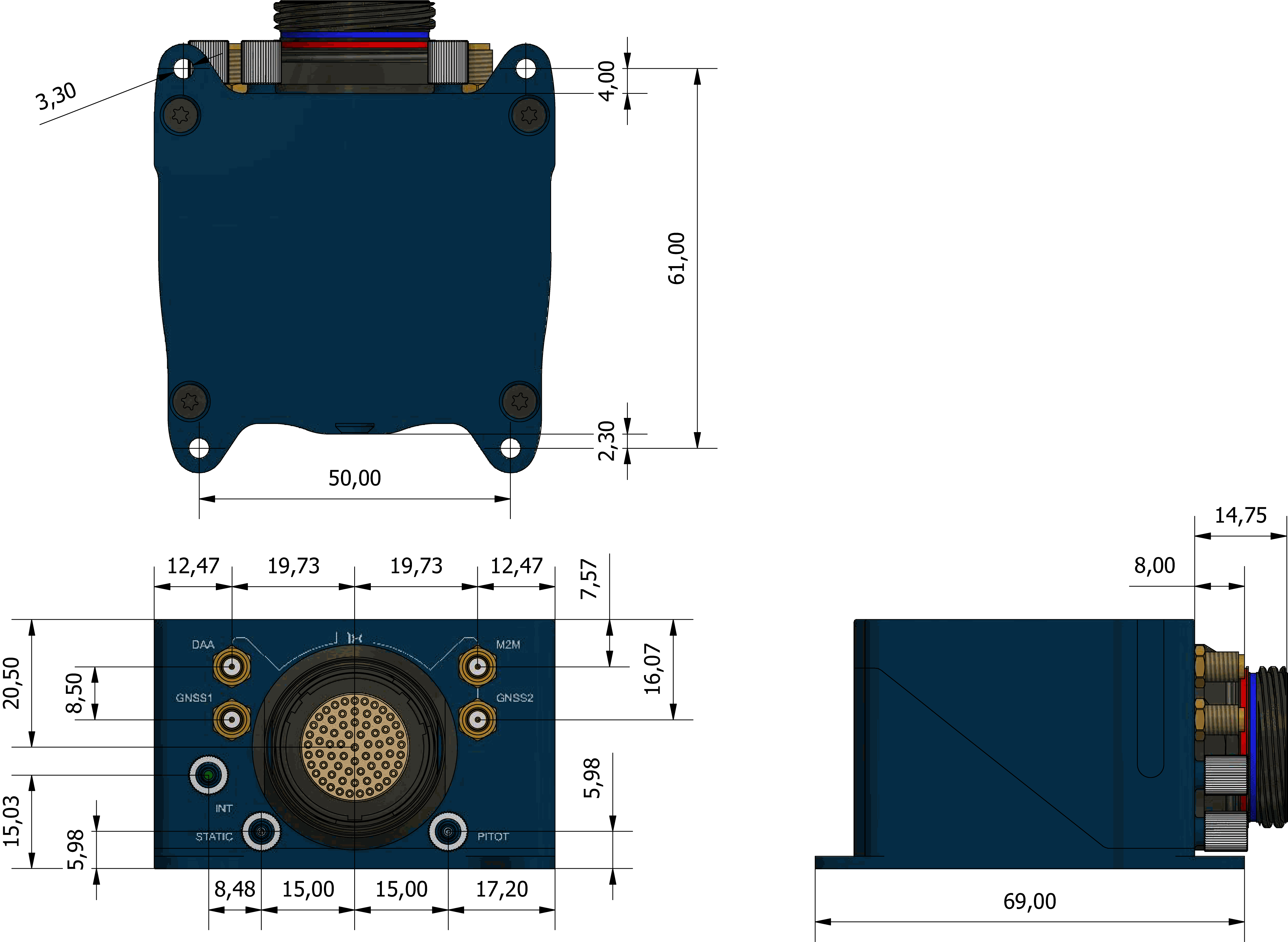
M3 screws are recommended for mounting. In saline environments such as coastal and oceanic, the screw material must be stainless steel.
Interfaces
Connector Layout
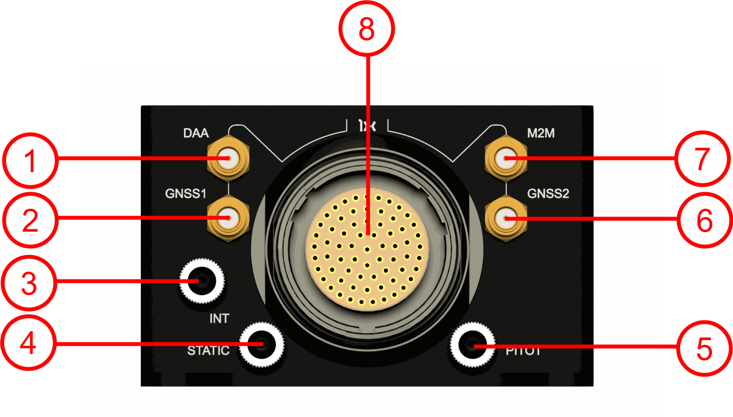
| Index | Connector |
|---|---|
| 1 |
ADS-B or Remote ID SSMA connector
Warning
When using ADS-B or Remote ID, there must be an adequate antenna or load connection to the DAA SMA. |
| 2 | GNSS1 SSMA connector
Note
This port is shared with the GNSS3 receiver. |
| 3 | Static pressure port (Int. D. 2.5 mm x Out. D. 4 mm) for static pressure sensor 2 |
| 4 | Static pressure port (Int. D. 2.5 mm x Out. D. 4 mm) for static pressure sensor 1 |
| 5 | Dynamic pressure port (Int. D. 2.5 mm x Out. D. 4 mm) |
| 6 | GNSS2 SSMA connector |
| 7 |
M2M SSMA connector
Warning
If the BLOS module is enabled, a suitable antenna must be connected to this SSMA port. The 4G Antenna with the Embention reference P000112 is recommended. |
| 8 | 68-pin connector |
Both static pressure ports must be used for sensor redundancy (Y tubing connection is strongly recommended). For detailed information, refer to the Pressure lines - Hardware Installation section of this manual.
Warning
The static pressure port 4 is always used by Autopilot 1x to calculate speed (using the difference of pressure between ports 4 and 5), no matter which sensor is selected in configuration.
Mating Connectors
| Index | Autopilot 1x Connector | Mating Connector |
|---|---|---|
| 1 | ADS-B or Remote ID (SSMA Jack Female) | SSMA male Plug, low-loss cable is recommended. |
| 2, 6 | GNSS antenna (SSMA Jack Female) | SSMA male Plug, low-loss cable is recommended. Active Antenna GNSS:
|
| 7 | M2M antenna (SSMA Jack Female) | SSMA male Plug, low-loss cable is recommended. |
| 8 | Connector HEW.LM.368.XLNP |
Mating connector: FGW.LM.368.XLCT (Embention reference P005550) Mating harnesses available on demand:
|
© 2025 Embention. All rights reserved.