Hardware Changelog
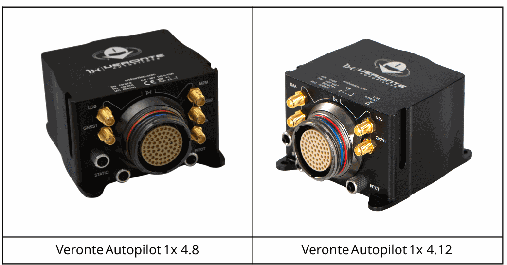
Hereby are described the main differences between the latest release of the Veronte Autopilot 1x hardware (v 4.12) and the previous commercial version (v 4.8).
Specifications
| Mechanical | ||
|---|---|---|
| 4.8 | 4.12 | |
| Mating connector | Circular mating connector with 68 pins | |
| Enclosure | Anodized aluminum | |
| Weight | W/O DAA variant: 198 g Remote ID variant: 210g ADS-B variant: 210g |
Remote ID variant: 208g ADS-B variant: 209g |
| Dimensions | 76 x 65 x 40 mm | |
| Protection rating | IP67 | |
| Mounting | M3 screws | |
| Temperature range (no convection) | -40 to 65 ºC | |
| Pressure port | SMC M5 series system. Usable with 2.5 x 4 mm polyurethane | |
| RF connectors | SSMA jack female | |
| I/O (on base hardware - expansion boards available) | ||
|---|---|---|
| 4.8 | 4.12 | |
| Vin | 2 x (6.5 - 36 V) DC | 2 x (8 - 54 V) DC |
| Vout | 5 & 3.3 V | |
| GNSS antenna power supply | 3.3V | 5V |
| PWM / GPIO | Up to 16 (3.3V) | Up to 8 (5V) |
| RS232 | 1 x | 2 x |
| RS485 | 1 x | 2 x |
| CAN bus | 2 x CAN 2.0 buses | 2 x CAN 2.0 buses 1 x CAN FD bus |
| I2C | 1 x | |
| FTS | Deadman output (GPIO) | Deadman output (GPIO) Dedicated power supply Independent datalink input |
| ADC | 5 x signals 3.3 V | 3 x signals 5 V 2 x signals 36 V |
| EQEP | 1 x | |
| UART | 1 x | 2 x |
| USB | 1 x | - |
| Ethernet | - | 1 x |
| LOS module | 1 x | - |
| BLOS module | 1 x | 1 x |
| Sensors | ||
|---|---|---|
| 4.8 | 4.12 | |
| Number of static pressure sensors | 2 | |
| Static pressure range |
1) 1,000 - 120,000 Pa 2) 30,000 - 120,000 Pa |
|
| Static pressure band error |
1) 500 Pa 2) 200 Pa |
|
| Static pressure resolution |
1) 1.2 to 6.5 Pa 2) 0.5 Pa |
|
| Number of dynamic pressure sensors | 1 | |
| Dynamic pressure range | 3 Pa (5 kt / 8 km/h sea level) to 6,900 Pa (206 kt / 382 km/h sea level) | |
| Dynamic pressure band error | 140 Pa | |
| Dynamic pressure resolution | 0.42 Pa | |
| Number of accelerometers (3 axis each) | 3 | 2 |
| Accelerometer range |
1) ±16 g 2) ±24 g 3) ±8 g |
2) ±24 g 3) ±8 g |
| Accelerometer max. shock |
1) 20,000 for 0.2 ms 2) 10,000 g/ms 3) 14,700 m/s² |
2) 10,000 g/ms 3) 14,700 m/s² |
| Accelerometer sensitivity |
1) 16,393 LSB/(m/s²) 2) 10,920 LSB/(m/s²) 3) 26,756,268 LSB/(m/s²) |
2) 10,920 LSB/(m/s²) 3) 26,756,268 LSB/(m/s²) |
| Number of gyroscopes (3 axis each) | 3 | 2 |
| Gyroscope range |
1) 125 to 2,000 º/s 2) 125 to 2,000 º/s 3) 2,000 º/s |
2) 125 to 2,000 º/s 3) 2,000 º/s |
| Gyroscope sensitivity |
1) 228 to 14.2 LSB/º/s 2) 262 to 16 LSB/º/s 3) 655,360 to 10 LSB/º/s |
2) 262 to 16 LSB/º/s 3) 655,360 to 10 LSB/º/s |
| Number of magnetometers | 3 | 2 |
| Magnetometer range |
0) 4 gauss 1) 8 gauss 2) 11 gauss |
0) 4 gauss 2) 11 gauss |
| Magnetometer sensitivity |
0) 6,842 to 1,711 LSB/gauss 1) 4,096 LSB/gauss 2) 0.13 mgauss |
0) 6,842 to 1,711 LSB/gauss 2) 0.13 mgauss |
| Number of GNSS units | 2 | 3 |
| GNSS constellations | 1) & 2) BeiDou, Galileo, GLONASS, GPS/QZSS |
1) & 2) BeiDou, Galileo, GLONASS, GPS, QZSS, SBAS 3) GPS + SBAS (compatible with WAAS, EGNOS, GAGAN, MSAS) |
| Concurrent GNSS constellations | 1) & 2) Up tp 4 constellations simultaneously |
1) & 2) Up tp 4 constellations simultaneously 3) 1 |
| GNSS bands | 1) & 2) L1 C/A, L2C, L1OF, L2OF, E1 B/C, E5b, B1I, B2I |
1) & 2) L1 C/A, L2C, L1OF, L2OF, E1 B/C, E5b, B1I, B2I 3) L1 C/A (1575.42 MHz) |
| RTK Suport | 1) & 2) Yes (via RTCM 3.x or PPP-RTK with SPARTN/CLAS) |
1) & 2) Yes (via RTCM 3.x or PPP-RTK with SPARTN/CLAS) 3) Not supported |
| RTK Position Accuracy | 1) & 2) 0.01 m + 1 ppm CEP |
1) & 2) 0.01 m + 1 ppm CEP 3) - |
| Update Rate | 1) & 2) RTK: Up to 5 Hz |
1) & 2) RTK: Up to 5 Hz 3) 4 Hz |
| Certificate | 1) & 2) No TSO certification |
1) & 2) No TSO certification 3) TSO-C199 Class B compliance |
Computing power
- Ram x 2: The available system memory (RAM) has been doubled (2x). This allows for more complex operations, larger mission profiles, and improved multitasking performance.
- Enhanced Processing Performance: Featuring an upgraded processor and an enhanced system architecture, the overall computing performance has been increased by over 25%. This provides more processing power for advanced navigation filters, onboard calculations, and future capabilities.
Sensors
- Enhanced GNSS modules: Which deliver higher precision and robustness, more accurate GNSS heading, improved jamming and spoofing detection, and enhanced RTK performance with better error reporting.
-
Added 3rd GNSS module with TSO C199 approval: A third, independent GNSS module has been incorporated, meeting FAA standards for TSO-C199. This adds a critical layer of redundancy and certified performance for demanding operations.
-
Enhanced magnetometer isolation: The magnetometer has been physically and electrically isolated from other onboard systems. This change significantly reduces magnetic interference, resulting in a more stable and reliable heading.
Integrated Independent SuC / FTS
A fully independent FTS / SuC module has been integrated directly into the hardware. This system is designed to provide a reliable safety mechanism that is segregated from the main autopilot functions.
- Compliance with Light-UAS.2511 Containment: Designed in accordance with EASA Light-UAS.2511 standards for containment, ensuring the aircraft can be commanded to remain within a defined operational volume.
-
Independent datalink input: The FTS operates on a dedicated power supply and utilizes an independent datalink input. This ensures its availability even in the event of a main power or primary datalink failure.
-
Includes a comprehensive suite of self-tests to verify the health and readiness of the termination system before flight.
Communications
- Enhanced LTE communications.
- Internal LOS module replaced by dedicated external LOS input. This new architecture allows users to connect a wider range of high-performance external LOS datalinks, offering greater flexibility and potentially improved RF performance by isolating the radio from onboard electronics.
Robustness & Certification
This version introduces significant improvements to the hardware's physical and electrical resilience, along with key compliance updates.
-
Enhanced Mechanical & Electrical Robustness: Autopilot 1x features a more robust physical construction, providing superior resistance to vibrations and shocks. Enhanced internal isolation has also been implemented to protect components and reduce interference.
-
Upgraded Power System Protection: Includes enhanced protection against inrush current during power up, reverse polarity on all inputs, and an improved power input redundancy scheme.
- Internal GNSS module with TSO compliance
- Enhanced Signal Control on Startup: To prevent unintended activation of motors or other actuators during the power-on or reset sequence, all configurable I/O pins are protected against high-impedance (floating) states. Each pin is equipped with a hardware pull-down resistor, ensuring it maintains a safe, known-low state until actively driven by the autopilot software.
Pinout changes from Autopilot 1x 4.8
The pinout for the 4.12 version features several important changes from the 4.8.
To prevent any confusion, the following table shows the pinout for both versions. The different pins are marked with ⚠️, all the rest have the same function.

| PIN | Signal | Type | Description |
|---|---|---|---|
| 1 ⚠️ |
I/O 0 | I/O | 4.8: PWM / Digital I/O signal (0-3.3V). Protected against ESD and short circuit.
Warning
Each pin withstands a maximum current of 1.65 mA. |
4.12: PWM / Digital I/O signal (0-5V). Protected against ESD and short circuit.
Warning
Each pin withstands a maximum current of 10 mA. |
|||
| 2 ⚠️ |
I/O 1 | I/O | 4.8: PWM / Digital I/O signal (0-3.3V). Protected against ESD and short circuit.
Warning
Each pin withstands a maximum current of 1.65 mA. |
4.12: PWM / Digital I/O signal (0-5V). Protected against ESD and short circuit.
Warning
Each pin withstands a maximum current of 10 mA. |
|||
| 3 ⚠️ |
I/O 2 | I/O | 4.8: PWM / Digital I/O signal (0-3.3V). Protected against ESD and short circuit.
Warning
Each pin withstands a maximum current of 1.65 mA. |
4.12: PWM / Digital I/O signal (0-5V). Protected against ESD and short circuit.
Warning
Each pin withstands a maximum current of 10 mA. |
|||
| 4 ⚠️ |
I/O 3 | I/O | 4.8: PWM / Digital I/O signal (0-3.3V). Protected against ESD and short circuit.
Warning
Each pin withstands a maximum current of 1.65 mA. |
4.12: PWM / Digital I/O signal (0-5V). Protected against ESD and short circuit.
Warning
Each pin withstands a maximum current of 10 mA. |
|||
| 5 ⚠️ |
I/O 4 | I/O | 4.8: PWM / Digital I/O signal (0-3.3V). Protected against ESD and short circuit.
Warning
Each pin withstands a maximum current of 1.65 mA. |
4.12: PWM / Digital I/O signal (0-5V). Protected against ESD and short circuit.
Warning
Each pin withstands a maximum current of 10 mA. |
|||
| 6 ⚠️ |
4.8: I/O 5 |
I/O | 4.8: PWM / Digital I/O signal (0-3.3V). Protected against ESD and short circuit.
Warning
Each pin withstands a maximum current of 1.65 mA. |
4.12: I/O 6 |
4.12: PWM / Digital I/O signal (0-5V). Protected against ESD and short circuit.
Warning
Each pin withstands a maximum current of 10 mA. |
||
| 7 ⚠️ |
4.8: I/O 6 |
I/O | 4.8: PWM / Digital I/O signal (0-3.3V). Protected against ESD and short circuit.
Warning
Each pin withstands a maximum current of 1.65 mA. |
4.12: I/O 5 |
4.12: PWM / Digital I/O signal (0-5V). Protected against ESD and short circuit.
Warning
Each pin withstands a maximum current of 10 mA. |
||
| 8 ⚠️ |
I/O 7 | I/O | 4.8: PWM / Digital I/O signal (0-3.3V). Protected against ESD and short circuit.
Warning
Each pin withstands a maximum current of 1.65 mA. |
4.12: PWM / Digital I/O signal (0-5V). Protected against ESD and short circuit.
Warning
Each pin withstands a maximum current of 10 mA. |
|||
| 9 | GND | GROUND | Ground signal for actuators 1-8 |
| 10 ⚠️ |
4.8: I/O 8 |
4.8: I/O |
4.8: PWM / Digital I/O signal (0-3.3V). Protected against ESD and short circuit.
Warning
Each pin withstands a maximum current of 1.65 mA. |
4.12: ETH_RX_P |
4.12: Input |
4.12: Ethernet. Receiver data positive. |
|
| 11 ⚠️ |
4.8: I/O 9 |
4.8: I/O |
4.8: PWM / Digital I/O signal (0-3.3V). Protected against ESD and short circuit.
Warning
Each pin withstands a maximum current of 1.65 mA. |
4.12: ETH_RX_N |
4.12: Input |
4.12: Ethernet. Receiver data negative. |
|
| 12 ⚠️ |
4.8: I/O 10 |
4.8: I/O |
4.8: PWM / Digital I/O signal (0-3.3V). Protected against ESD and short circuit.
Warning
Each pin withstands a maximum current of 1.65 mA. |
4.12: ETH_TX_P |
4.12: Output |
4.12: Ethernet. Transceiver data positive. |
|
| 13 ⚠️ |
4.8: I/O 11 |
4.8: I/O |
4.8: PWM / Digital I/O signal (0-3.3V). Protected against ESD and short circuit.
Warning
Each pin withstands a maximum current of 1.65 mA. |
4.12: ETH_TX_N |
4.12: Output |
4.12: Ethernet. Transceiver data negative. |
|
| 14 ⚠️ |
4.8: I/O 12 |
4.8: I/O |
4.8: PWM / Digital I/O signal (0-3.3V). Protected against ESD and short circuit.
Warning
Each pin withstands a maximum current of 1.65 mA. |
4.12: ETH_CHASSIS |
4.12: GROUND |
4.12: Ethernet chassis (this pin is electrically connected to the external cover of the ethernet cable). |
|
| 15 ⚠️ |
4.8: I/O 13 |
4.8: I/O |
4.8: PWM / Digital I/O signal (0-3.3V). Protected against ESD and short circuit.
Warning
Each pin withstands a maximum current of 1.65 mA. |
4.12: CANFD_P |
4.12: I/O |
4.12: High signal of CAN FD bus interface, up to 5 Mbps (2.75 - 4.5 V). Protected against ESD. Twisted pair with a 120 ohms Zo recommended. |
|
| 16 ⚠️ |
4.8: I/O 14 |
4.8: I/O |
4.8: PWM / Digital I/O signal (0-3.3V). Protected against ESD and short circuit.
Warning
Each pin withstands a maximum current of 1.65 mA. |
4.12: CANFD_N |
4.12: I/O |
4.12: Low signal of CAN FD bus interface (0.5 - 2.25 V). Protected against ESD. Twisted pair with a 120 ohms Zo recommended. |
|
| 17 ⚠️ |
4.8: I/O 15 |
4.8: I/O |
4.8: PWM / Digital I/O signal (0-3.3V). Protected against ESD and short circuit.
Warning
Each pin withstands a maximum current of 1.65 mA. |
4.12: ARB_TX |
4.12: NC |
4.12: (SuC UART) Reserved. Do not connect. |
|
| 18 | GND | GROUND | Common ground. |
| 19 ⚠️ |
4.8: RS 232 TX |
Output | 4.8: RS 232 Output (-13.2V to 13.2V Max, -5.4V to 5.4V Typical). Protected against ESD and short circuit. |
4.12: RS232 1 TX |
4.12: RS 232 channel 1 Output (-13.2V to 13.2V Max, -5.4V to 5.4V Typical). Protected against ESD and short circuit. |
||
| 20 ⚠️ |
4.8: RS 232 RX |
Input | 4.8: RS 232 Input (-25V to 25V Max, -0.6V Low and 2.4V High Threshold). Protected against ESD and short circuit. |
4.12: RS232 1 RX |
4.12: RS 232 channel 1 Input (-25V to 25V Max, -0.6V Low and 2.4V High Threshold). Protected against ESD and short circuit. |
||
| 21 | GND | GROUND | Ground signal for buses. |
| 22 ⚠️ |
ANALOG_3 | Input Analog | 4.8: Input 0-3.3V. Protected against ESD. |
4.12: Input 0-36V. Protected against ESD. |
|||
| 23 ⚠️ |
ANALOG_4 | Input Analog | 4.8: Input 0-3.3V. Protected against ESD. |
4.12: Input 0-36V. Protected against ESD. |
|||
| 24 | GND | GROUND | Ground signal for buses. |
| 25 | CANA_P | I/O | High signal of CAN 2.0 bus interface, up to 1 Mbps. Protected against ESD. Twisted pair with a 120 ohms Zo recommended. |
| 26 | CANA_N | I/O | Low signal of CAN 2.0 bus interface, up to 1 Mbps. Protected against ESD. Twisted pair with a 120 ohms Zo recommended. |
| 27 ⚠️ |
4.8: 4XV_WD |
4.8: I/O |
4.8: Reserved. Do not connect. |
4.12: UART_RX |
4.12: Input |
4.12: Microcontroller UART. |
|
| 28 | CANB_P | I/O | High signal of CAN 2.0 bus interface, up to 1 Mbps. Protected against ESD. Twisted pair with a 120 ohms Zo recommended. |
| 29 | CANB_N | I/O | Low signal of CAN 2.0 bus interface, up to 1 Mbps. Protected against ESD. Twisted pair with a 120 ohms Zo recommended. |
| 30 | GND | GROUND | Ground signal for buses. |
| 31 | I2C_CLK | Output | Clk line for I2C bus (0.3V to 3.3V). Protected against ESD |
| 32 | I2C_DATA | I/O | Data line for I2C bus (0.3V to 3.3V). Protected against ESD |
| 33 | GND | GROUND | Ground for 3.3V power supply. |
| 34 | 3.3V | POWER | 3.3V - 100mA power supply. Protected against ESD short circuit with 100mA resettable fuse. |
| 35 | GND | GROUND | Ground for 5V power supply. |
| 36 | 5V | POWER | 5V - 100mA power supply. Protected against ESD short circuit with 100mA resettable fuse. |
| 37 | GND | GROUND | Ground for analog signals. |
| 38 ⚠️ |
ANALOG_0 | Input | 4.8: Input 0-3.3V. Protected against ESD. |
4.12: Input 0-5V. Protected against ESD. |
|||
| 39 ⚠️ |
ANALOG_1 | Input | 4.8: Input 0-3.3V. Protected against ESD. |
4.12: Input 0-5V. Protected against ESD. |
|||
| 40 ⚠️ |
ANALOG_2 | Input | 4.8: Input 0-3.3V. Protected against ESD. |
4.12: Input 0-5V. Protected against ESD. |
|||
| 41 ⚠️ |
4.8: 4XV_A |
4.8: I/O |
4.8: Reserved. Do not connect. |
4.12: SEL |
4.12: Input |
4.12: Reserved. Do not connect. |
|
| 42 | FTS1_OUT | Output | Deadman signal from comicro. Protected against ESD and short circuit. |
| 43 | FTS2_OUT | Output | !SystemOK Bit. Protected against ESD and short circuit. |
| 44 ⚠️ |
4.8: 4XV_B |
4.8: I/O |
4.8: Reserved. Do not connect. |
4.12: SEL |
4.12: Input |
4.12: Reserved. Do not connect. |
|
| 45 ⚠️ |
4.8: UARTA_TX |
4.8: Output |
4.8: Microcontroller UART. |
4.12: RS232 2 TX |
4.12: Output |
4.12: RS 232 channel 2 Output (-13.2V to 13.2V Max, -5.4V to 5.4V Typical). Protected against ESD and short circuit. |
|
| 46 ⚠️ |
4.8: UARTA_RX |
4.8: Input |
4.8: Microcontroller UART. |
4.12: RS232 2 RX |
4.12: Input |
4.12: RS 232 channel 2 Input (-25V to 25V Max, -0.6V Low and 2.4V High Threshold). Protected against ESD and short circuit. |
|
| 47 | GND | GROUND | Ground signal comicro power supply |
| 48 ⚠️ |
V_ARB_VCC | POWER | 4.8: Veronte comicro power (6.5V to 36V). Protected against ESD and reverse polarity. |
4.12: Veronte comicro power (8V to 54V). Protected against ESD and reverse polarity. |
|||
| 49 ⚠️ |
4.8: FTS3_OUT_MPU |
4.8: Output |
4.8: MPU alive voting signal, to use with 4xVeronte. It is a Square Wave at [100,125] Hz. Protected against ESD and short circuit. |
4.12: UART_TX |
4.12: Output |
4.12: Microcontroller UART. |
|
| 50 ⚠️ |
4.8: OUT_RS485_P |
Output | 4.8: Non-inverted output from RS485 bus. Protected against ESD. |
4.12: OUT RS485 A_P |
4.12: Non-inverted output from RS485 bus A. Protected against ESD. |
||
| 51 ⚠️ |
4.8: OUT_RS485_N |
Output | 4.8: Inverted output from RS485 bus. Protected against ESD. |
4.12: OUT RS485 A_N |
4.12: Inverted output from RS485 bus A. Protected against ESD. |
||
| 52 ⚠️ |
4.8: IN_RS485_N |
Input | 4.8: Inverted input from RS485 bus. Protected against ESD. |
4.12: IN RS485 A_N |
4.12: Inverted input from RS485 bus A. Protected against ESD. |
||
| 53 ⚠️ |
4.8: IN_RS485_P |
Input | 4.8: Non-Inverted input from RS485 bus. Protected against ESD. |
4.12: IN RS485 A_P |
4.12: Non-Inverted input from RS485 bus A. Protected against ESD. |
||
| 54 | GND | OUT_GND | Ground for RS-485 bus.
Warning
This is not a common GND pin. |
| 55 ⚠️ |
EQEP_A | I/O | 4.8: DIGITAL output / DIGITAL input / Encoder quadrature input A (0-3.3V). Protected against ESD and short circuit. |
4.12: DIGITAL output / DIGITAL input / Encoder quadrature input A (0-5V). Protected against ESD and short circuit.
Warning
Configured as oputput, it withstands a maximum current of 1.65 mA. |
|||
| 56 ⚠️ |
EQEP_B | I/O | 4.8: DIGITAL output / DIGITAL input / Encoder quadrature input B (0-3.3V). Protected against ESD and short circuit. |
4.12: DIGITAL output / DIGITAL input / Encoder quadrature input B (0-5V). Protected against ESD and short circuit.
Warning
Configured as oputput, it withstands a maximum current of 1.65 mA. |
|||
| 57 ⚠️ |
EQEP_S | I/O | 4.8: DIGITAL output / DIGITAL input / Encoder quadrature input strobe (0-3.3V). Protected against ESD and short circuit. |
4.12: DIGITAL output / DIGITAL input / Encoder quadrature input strobe (0-5V). Protected against ESD and short circuit.
Warning
Configured as oputput, it withstands a maximum current of 1.65 mA. |
|||
| 58 ⚠️ |
EQEP_I | I/O | 4.8: DIGITAL output / DIGITAL input / Encoder quadrature input index (0-3.3V). Protected against ESD and short circuit. |
4.12: DIGITAL output / DIGITAL input / Encoder quadrature input index (0-5V). Protected against ESD and short circuit.
Warning
Configured as oputput, it withstands a maximum current of 1.65 mA. |
|||
| 59 | GND | GROUND | Ground for encoders |
| 60 ⚠️ |
4.8: V_USB_DP |
4.8: I/O |
4.8: Veronte USB data line. Protected against ESD. |
4.12: OUT RS485 B_P |
4.12: Output |
4.12: Non-inverted output from RS485 bus B. Protected against ESD and short circuit. |
|
| 61 ⚠️ |
4.8: V_USB_DN |
4.8: I/O |
4.8: Veronte USB data line. Protected against ESD. |
4.12: OUT RS485 B_N |
4.12: Output |
4.12: Inverted output from RS485 bus B. Protected against ESD and short circuit. |
|
| 62 ⚠️ |
4.8: USB_SHIELD_GND |
4.8: GROUND |
4.8: USB cable shielding. |
4.12: IN RS485 B_N |
4.12: Input |
4.12: Inverted input from RS485 bus B. Protected against ESD and short circuit. |
|
| 63 ⚠️ |
4.8: FTS_OUT_MPU |
4.8: Output |
4.8: Abort mission voting signal from MPU, to use with 4xVeronte. Bit Low (0V) if mission OK. High (3.3V) if mission wants to be terminated. Protected against ESD and short circuit. |
4.12: IN RS485 B_P |
4.12: Input |
4.12: Non-inverted input from RS485 bus B. Protected against ESD and short circuit. |
|
| 64 ⚠️ |
4.8: FTS2_OUT_MPU |
4.8: Output |
4.8: Abort mission voting signal 2 from MPU, to use with 4xVeronte. Bit Low (0V) if mission OK. High (3.3V) if mission wants to be terminated. Protected against ESD and short circuit. |
4.12: ARB_RX |
4.12: NC |
4.12: (SuC UART) Reserved. Do not connect. |
|
| 65 | GND | GROUND | Veronte ground input |
| 66 | GND | GROUND | Veronte ground input |
| 67 ⚠️ |
VCC | POWER |
4.8: Veronte power supply (6.5V to 36V). Protected against ESD and reverse polarity.
Warning
Pins 67 and 68 are common. They MUST be connected to the same power supply. 4.12: Veronte power supply (8V to 54V). Protected against ESD and reverse polarity.
Warning
Pins 67 and 68 are common. They MUST be connected to the same power supply. |
| 68 ⚠️ |
VCC | POWER |
Warning
Remember!! All GND pins are common. Note that pin 54 is not a common GND pin.
© 2025 Embention. All rights reserved.