GNSS Receivers
NexNav GNSS
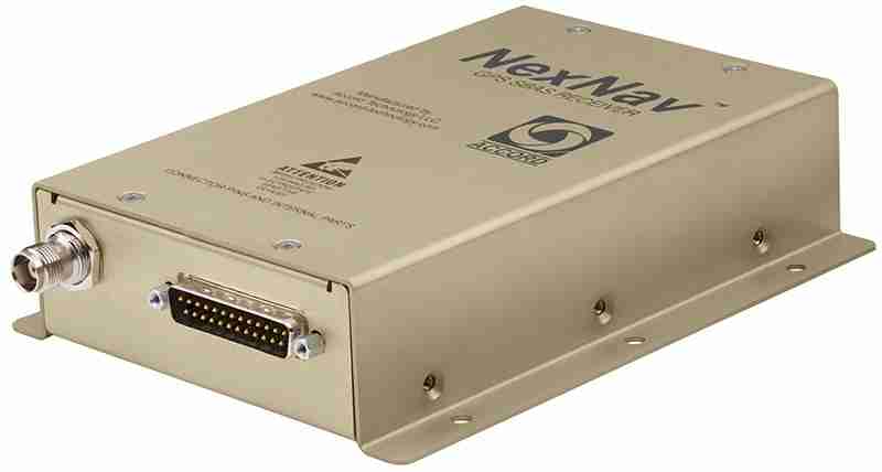
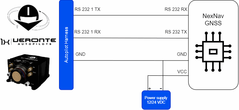
NexNav GNSS sensor integrates with Autopilot 1x via RS232 connection.
Important
Note that it must be connected to an external power supply, sharing signal ground with Autopilot 1x.
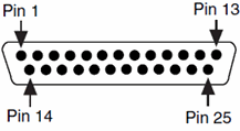
| Autopilot 1x Harness | NexNav GNSS Connector | |||
|---|---|---|---|---|
| PIN | Signal | Color Code | PIN | Signal |
| 19 | RS232 1 TX | White-Pink | 20 | RS-232 RX, Port 1 |
| 20 | RS232 1 RX | Pink-Brown | 7 | RS-232 TX, Port 1 |
| 21 | GND | White-Blue | 10 | RS-232 Ground |
Note
The user has the option to configure either of the two available RS-232 lines on the Autopilot 1x: RS 232 1 or RS 232 2. For more information about these pins, refer to the Pinout - Hardware Installation section of the present manual.
Warning
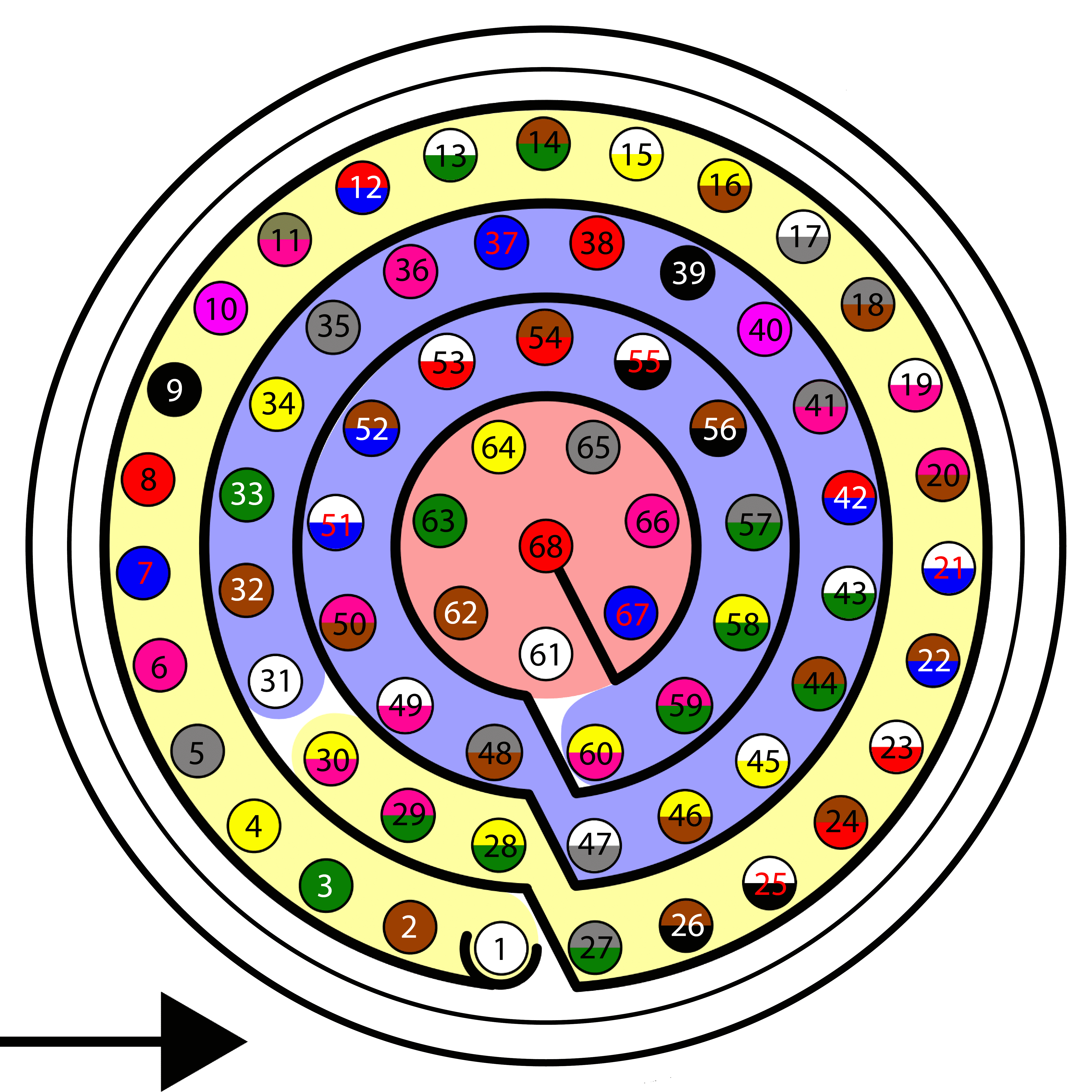
Remember!! In Autopilot 1x, all GND pins are common. Note that pin 54 is not a common GND pin.
The software installation of this device with Autopilot 1x is explained in the NexNav GNSS - Integration examples section of the 1x PDI Builder user manual.
© 2025 Embention. All rights reserved.