Technical
Main Features
- Configuration parameters: for reduced power consumption.
The block diagram of the system is shown below.
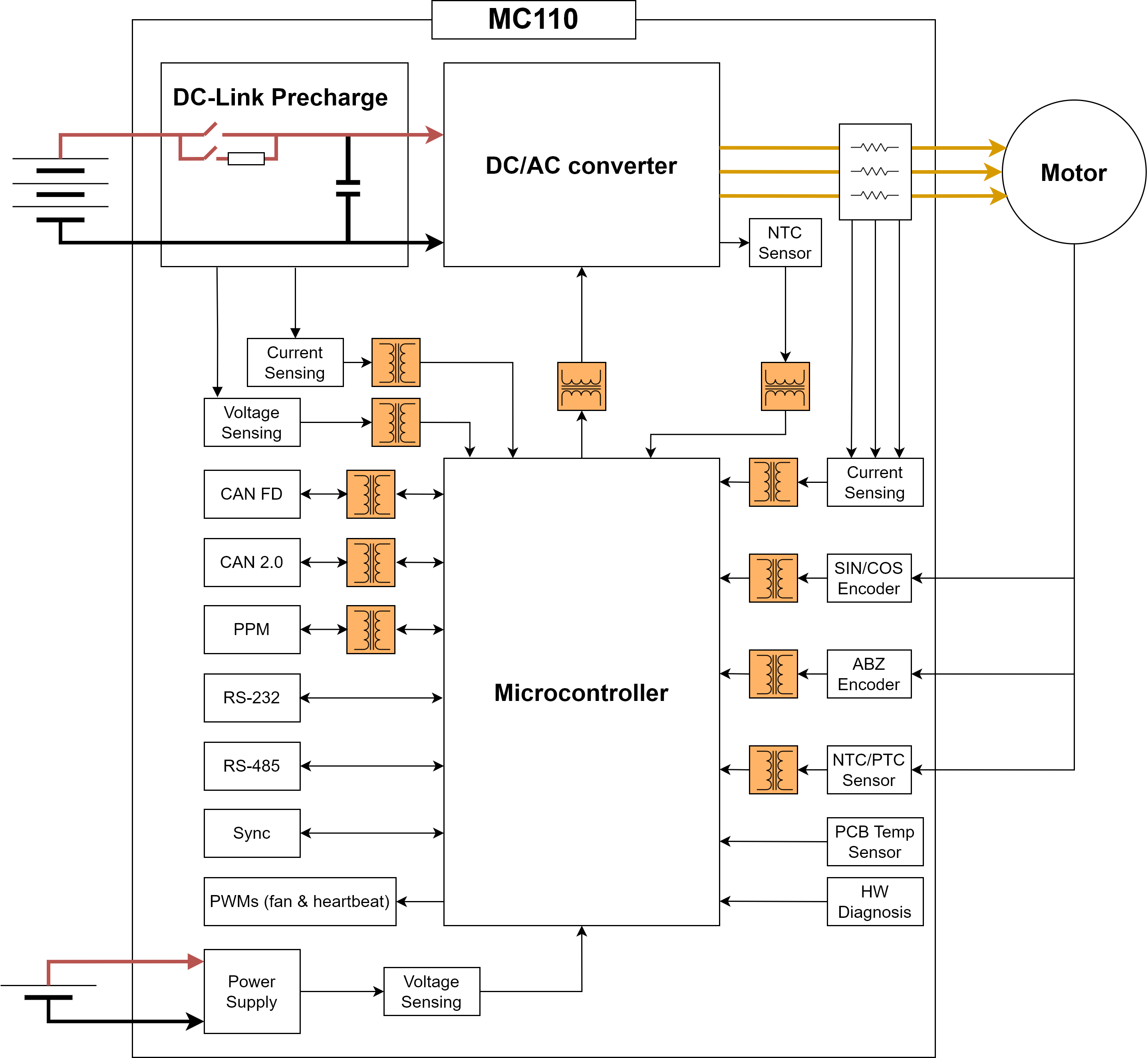
Peripheral used for motor control:
- PWM signal, optocupled inside the MC110
- CAN bus
- CAN FD bus
Peripheral use for ESC telemetry:
- Serial RS-232
- Serial RS-485
Any of the serial interfaces can be used to configure the internal variables of the MC110.
Mechanical Specifications
- Weight: 2680 g
- Maximum speed (for 1 pair of poles) 50,000 RPM (depending on the acquisition frequency)
-
Dimensions:
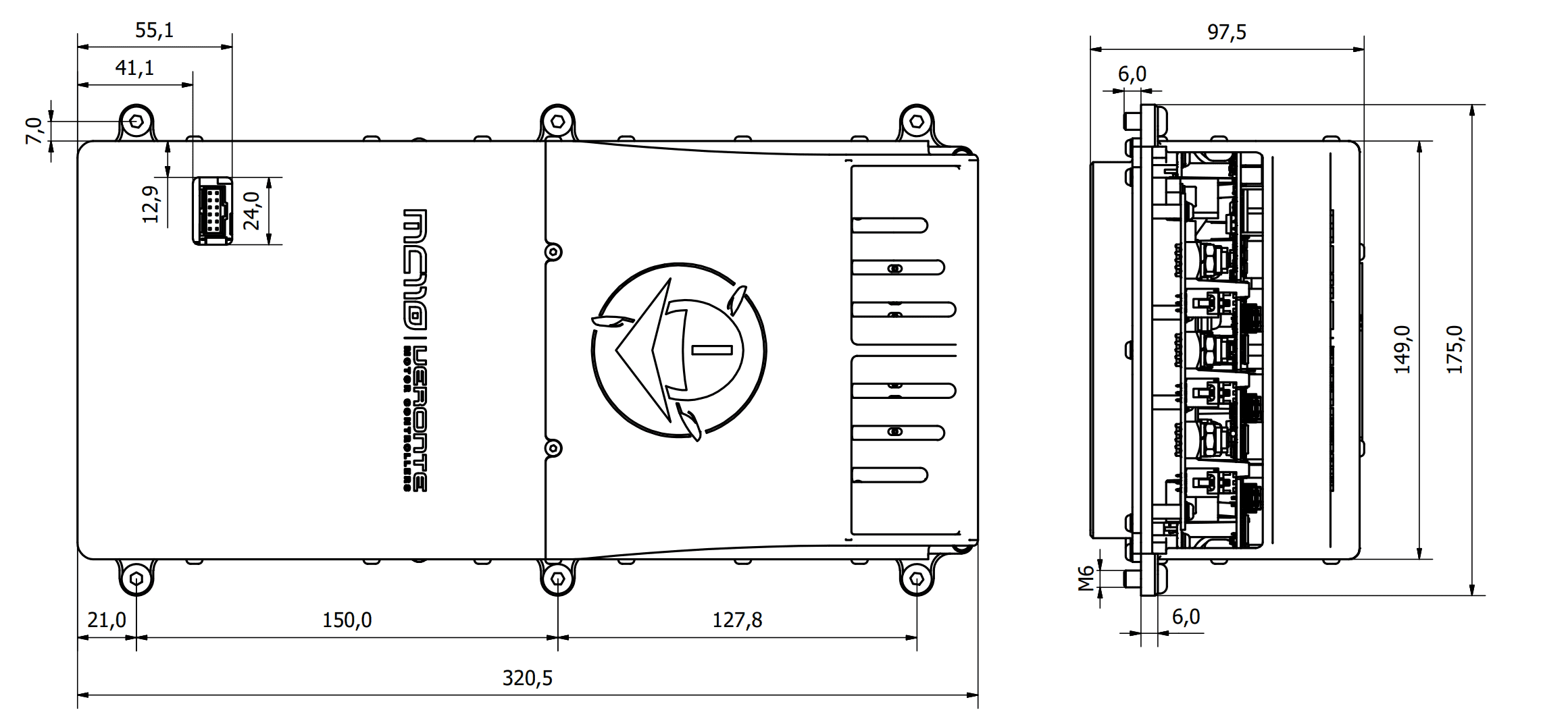
Dimensions in mm
Electrical Specifications
- Power: up to 110 kW *
- Maximum continous current: Up to 200A*
- Peak current: 250A (as long as MC110 is not overheated by the input power)
- PWM Frequency: 5-24 kHz
- HV range: 100 V to 800 V
- LV range: 8 V to 36 V
- Minimum temperature: - 30 ºC
- Maximum temperature: 150 ºC * (for IGBT module)
- Regenerative brake: 60 A maximum
-
Sensorless mode: MC110 is able to operate with sensorless motors with maximum efficiency.
The sensorless mode does not require a minimum speed to measure it and operate, as long as MC110 provides current to the motor phases (since the speed is measured with the current).
Note
Features with * depend on voltage and switching frequency. To know more, read the Maximum continuous current section below.
-
Protections:
- Protection agains in-rush current when turned on (at low and at high voltage sides)
- Ground fault detection
- Protection against overcurrent at power input and phases
-
Sensored motors:
- Hall sensors
- Digital incremental encoders
- Analog SIN/COS
-
Reverse rotation: MC110 can operate in any direction of rotation without additional configuration.
-
Configurable:
- Type of Observer
- Programmable acceleration curve
- Motor direction
- Overvoltage threshold
- Overcurrent threshold
- Overtemperature threshold
- Max. RPM (limit)
- Braking force
- Duty Cycle
-
Communications:
- CAN Bus
- CAN FD Bus
- PWM optocupled inside the MC110
- RS-232
- RS-485
-
Redundant control
- Telemetry:
- Motor & ESC temperature
- RPM
- Input voltage
- Input and output current
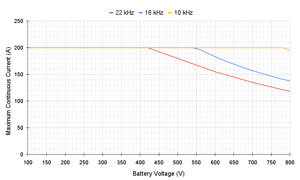
Maximum continuous current
The relationship between maximum input current and battery voltage depends on the switching frequency of the DC/AC converter. The following figure shows this relationship for different switching frequencies.
Interfaces
HALL Inputs
Warning
The employed hall sensors must not exceed 5 V.
These inputs are used to add to the system a feedback in sensored mode (incremental type, usually magnetic).
The 3 Hall effect sensors must be placed at 120° (electrical degrees) from each other. The following is a simple formula for obtaining the mechanical degrees of separation when installing the sensors:
So the sensors must be placed one of each other at:
For example, for 10 pole pairs:
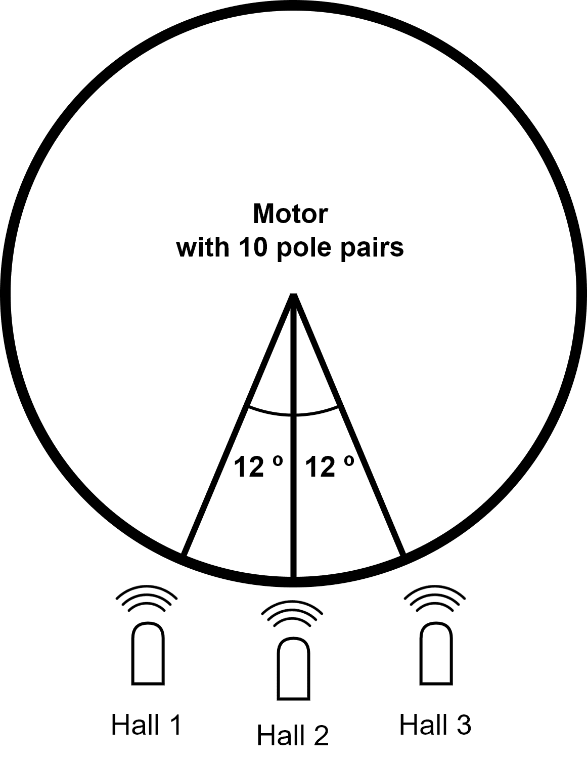
Tip
The arc length between sensors can be calculated as follows:
FAN_PWM
This Open-Drain output is used to control an external fan if needed. External power for the fan and an aditional pull-up resistor is required. Maximum voltage in this signal is 60 V and 360 mA for maximum sink current. It is important that the GND connection of this supply is the same as the GND connection for the supply of the control group (user connector).
Opto PWM Input
This input is an optocoupled control digital signal.
The input is interpreted as 0-100 % of the maximum RPM. An initial dead band can be configured to prevent the engine from starting.
| Type | Specification |
|---|---|
| Input voltage range | 0-5 V |
| Minimum input current | 2.5 mA |
| Pulse length | 1-2 ms |
| Frequency | 40-250 Hz |
NTC/PTC Input (External Temperature Sensing)
A PTC or NTC can be integrated. The PTC or NTC must not exceed 2 V.
The PTC/NTC should be connected on the low side of an external resistor divider. This is the configuration by default. A high side connection can be used too, but a custom modification is needed.
The isolated Voltage_ref output should be left floating in default mode. The iso_ground is the return path of the NTC/PTC sensor.
SIN/COS_SIGNAL
These signals are those dedicated to the SIN / COS type analog sensor.
Warning
SIN/COS signals must not exceed 5 V.
RS-232
Single ended serial type protocol:
| Type | Specification |
|---|---|
| ESD Protection | ±15 kV (HBM) |
| Requirements | TIA/EIA-232-F and ITU v.28 |
| Speed | Max. 250 kbit/s |
| Input Voltage | -25 to 25 V |
| Output Voltage | -13.2 to 13.2 V |
RS-485
Differential serial type protocol:
| Type | Specification |
|---|---|
| ESD Protection | ±15 kV (HBM) |
| Requirements | TIA/EIA-485-A |
| Speed | Max. 25 Mbit/s |
| Input Voltage (D) | -0.5 to 7 V |
| Output Voltage (D) | 1.5 to 2.4 V |
Isolated CAN FD and Isolated CAN 2.0
Differential communication protocol with flexible data rate:
| Type | Specification |
|---|---|
| ESD Protection | ±4 kV (HBM) |
| Requirements | ISO11898-2 |
| Speed | Max. 5 Mbit/s |
| Max CAN 2.0 Speed | 1 Mbit/s |
| Input Voltage (D) | -12 to 12 V |
| CAN H Voltage | 2.75 to 4.5 V |
| CAN L Voltage | 0.5 to 2.25 V |
Connector Layout
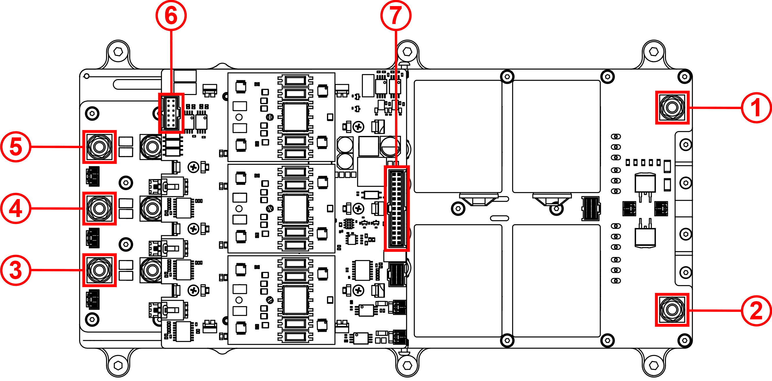
| Index | Connector | |
|---|---|---|
| Power | 1 | HV negative |
| 2 | HV positive | |
| 3 | Phase U Connector | |
| 4 | Phase V Connector | |
| 5 | Phase W Connector | |
| Electronic | 6 | Sensor Connector |
| 7 | User Connector |
Mating Connectors
| Index | MC110 Connector | Mating Connector | |
|---|---|---|---|
| Power | 1 | HV negative | Tubular cable lugs of Würth with M6. The recommended reference depends on wire section:
|
| 2 | HV positive | ||
| 3 | Phase U Connector | ||
| 4 | Phase V Connector | ||
| 5 | Phase W Connector | ||
| Electronic | 6 | Sensor Connector Molex: 90130-1312 |
Mating connector - Molex: 90142-0012 Mating harness available on demand: Conn Harness MC110 2.0 (Embention reference P008609) |
| 7 | User Connector Molex: 90130-1130 |
Mating connector - Molex: 90142-0030 Mating harnesses available on demand:
|
© 2025 Embention. All rights reserved.