Hardware Installation
Danger
The dc-link capacitors may remain charged with hazardous voltage after the power source is disconnected. Wait at least 5 minutes for the internal passive resistors to fully discharge the capacitors before handling the connections.
Note
When working voltage is higher than 60 V, use of insulating gloves are mandatory for installation and the system must have a chassis fault detection system.
Mechanical
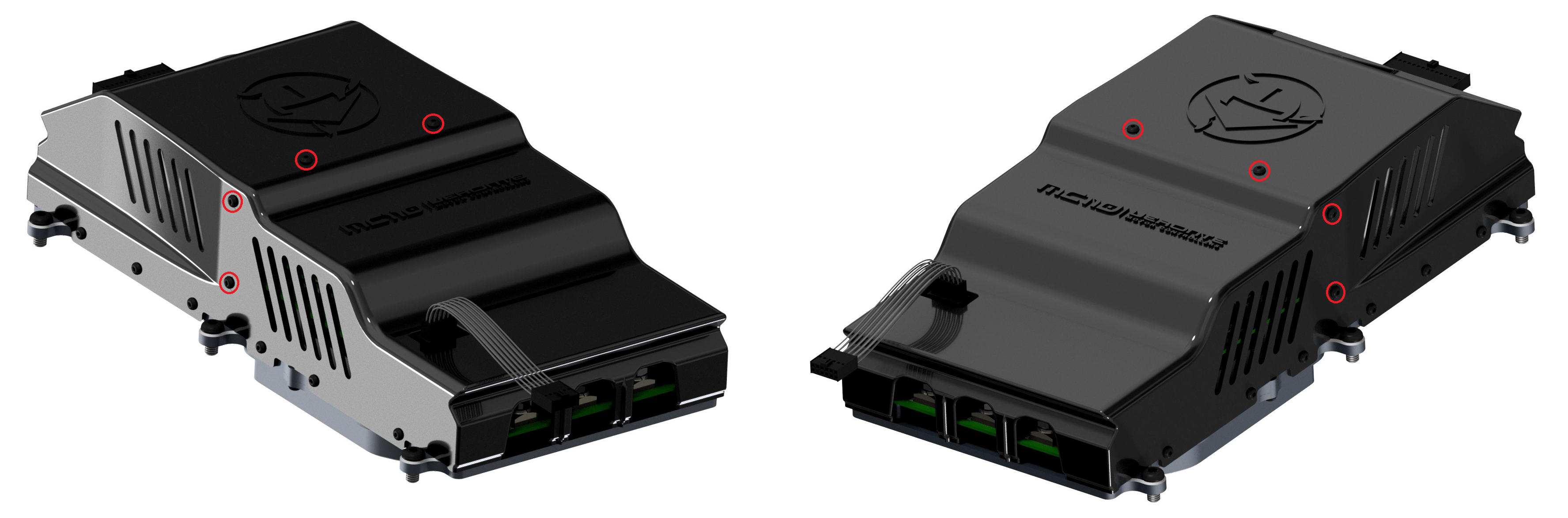
To fix the MC110 to an aircraft frame, take a look to the dimensions and screws positions. Screw holes must be deeper than 6 mm with M6.
Electrical
ESC-Motor Wiring
Warning
The polarity connection of the input must be respected, otherwise a short circuit may occur.
The polarity and connections are indicated in the following image and table.
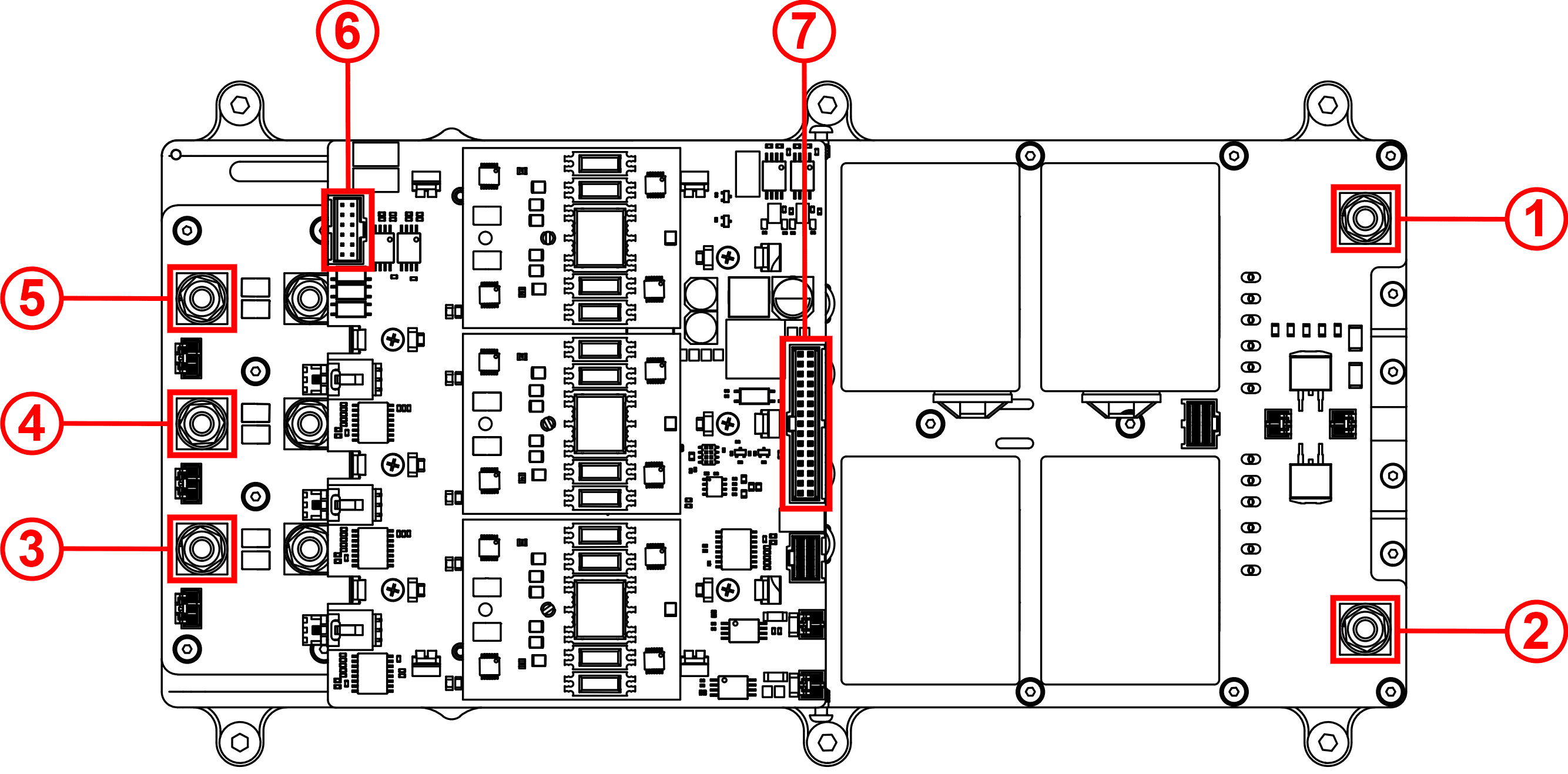
| Index | Connector | Description |
|---|---|---|
| 1 | HV negative | Input power from DC current 100 to 800 V DC |
| 2 | HV positive | |
| 3 | Phase U Connector | Output power to motor |
| 4 | Phase V Connector | |
| 5 | Phase W Connector | |
| 6 | Sensor Connector | Encoders and sensor temperature signals |
| 7 | User Connector | Communications, telemetry and control signals |
Note
The section of the cables must be dimensioned according to the maximum power that will be used
Warning
When using a power supply that does not have sink capabilities (cannot absorb current), the regenerative functions of the MC110 must be turned OFF to prevent damage to the power supply. For additional protection, it is recommended to install a diode in series between the positive terminal of the power supply and the HV positive input of the MC110.
Battery cables between MC and battery should be as short as possible. If the distance between battery and motor is long, please extend phase cables in order to shorten battery cables.
Tip
Connection of the phases can be done freely, however, it will affect the direction of rotation of the motor. Hence, if the motor is spinning in the opposite direction, switch any 2 phases around.
User Connector Wiring
Note
The user must not remove the screws that hold the two casings together.
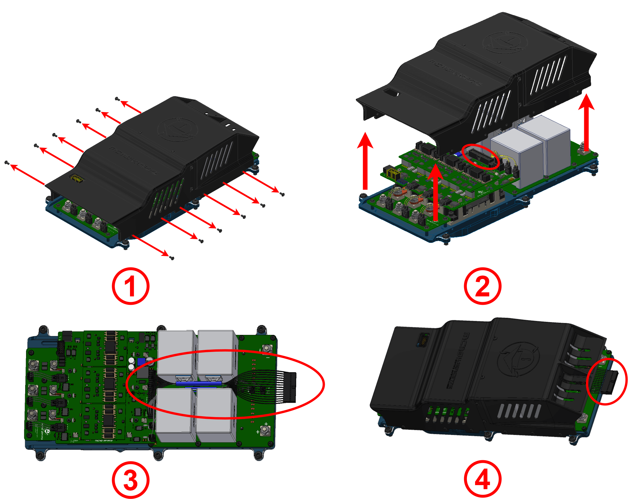
To access and wire the user connector, follow the next steps:
-
Unscrew the enclosure.
-
Pull up the enclosure and plug the user connector.
-
Pass the wires between the capacitors. Heat shrinkable cover is recommended to protect wires and keep them together.
Tip
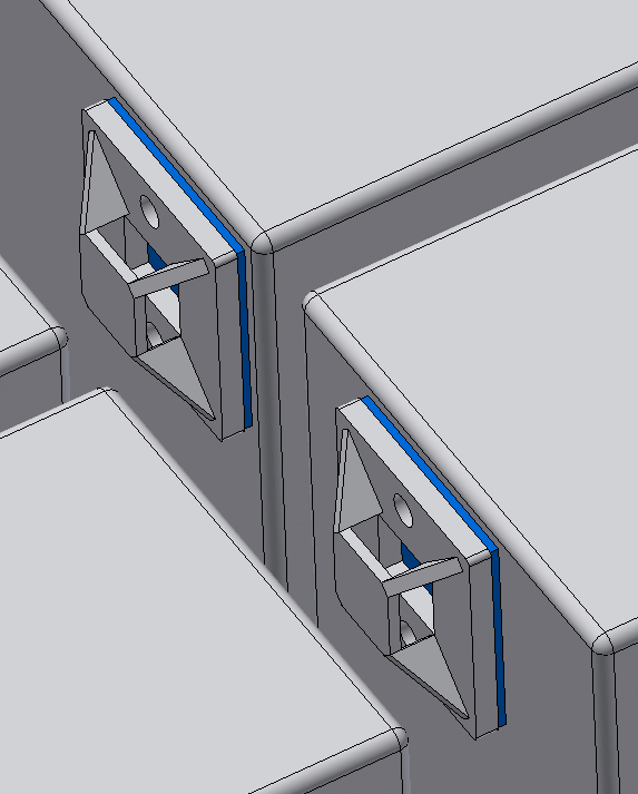
The capacitors have two cable tie mounts, so wires can be fixed with cable ties.
-
Screw back the enclosure, such that wires protrudes from MC110.
Important
When reinstalling the housing, apply a medium-strength fastener to these screws and tighten to a torque of 0.2 Nm.
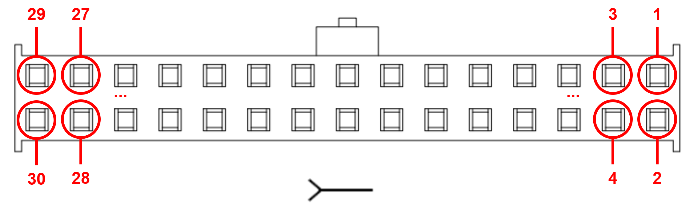
Pinout
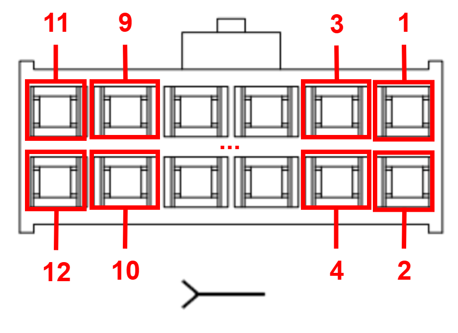
User Connector pinout
The user connector pinout is shown in the following figure and table:
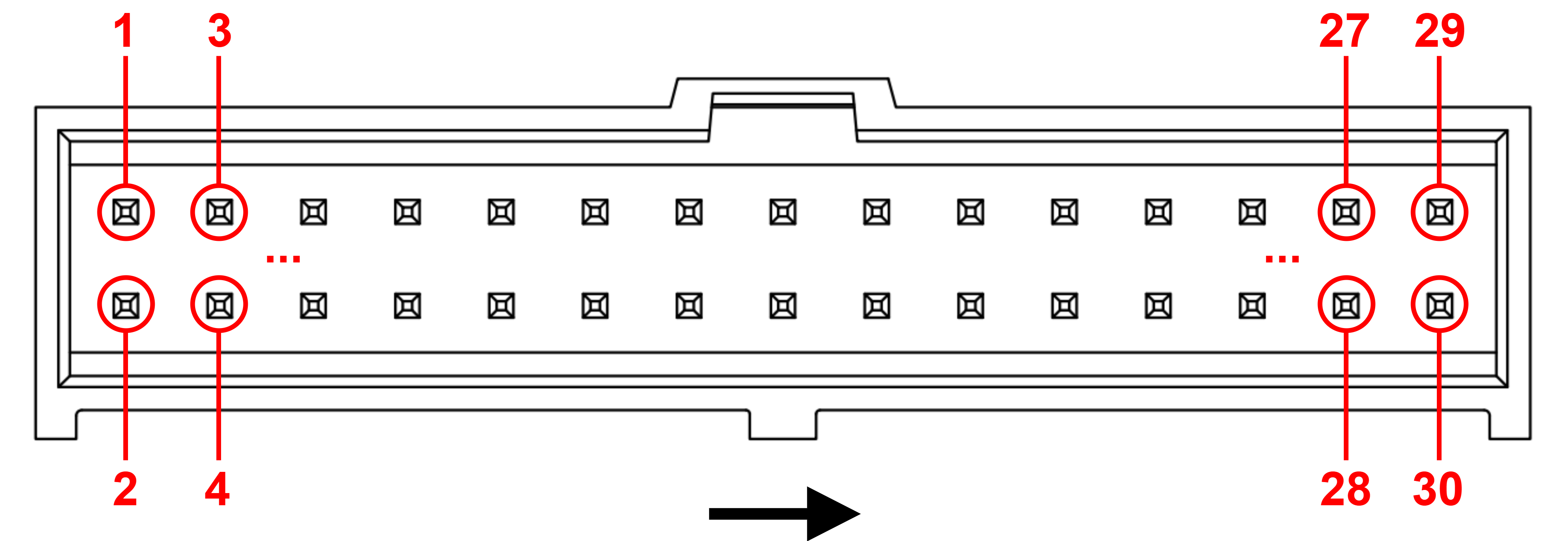
| PIN | Signal | Description | PIN | Signal | Description |
|---|---|---|---|---|---|
| 1 | HRBT_OUT * | Output PWM Heartbeat signal to synchronize multiple MC110 units | 2 | HRBT_IN * | Input PWM Heartbeat signal to synchronize multiple MC110 units |
| 3 | GND | Ground | 4 | GND | Ground |
| 5 | SYNC_OUT * | Output PWM to synchronize multiple MC110 units | 6 | SYNC_IN * | Input PWM to synchronize multiple MC110 units |
| 7 | GND | Ground | 8 | RS232_TX | RS-232 transmitter |
| 9 | OUT_485_P | RS-485 output positive | 10 | RS232_RX | RS-232 receiver |
| 11 | OUT_485_N | RS-485 output negative | 12 | FAN_PWM | Digital PWM output for fan control |
| 13 | IN_485_N | RS-485 input negative | 14 | GPIO_AUX | Auxiliar GPIO signal |
| 15 | IN_485_P | RS-485 input positive | 16 | GND_485 | Ground for RS-485 |
| 17 | OPTO_PWM | Digital Input for motor speed. Optocoupled inside MC110 | 18 | OPTO_RTN | Return of pin 17 |
| 19 | CANFD_N | CAN FD negative pin | 20 | CANFD_P | CAN FD positive pin |
| 21 | 22 | ||||
| 23 | GND_CAN ** | Isolated ground for CAN | 24 | GND_CAN ** | Isolated ground for CAN |
| 25 | CANB_N | CAN B negative pin | 26 | CANB_P | CAN B positive pin |
| 27 | 28 | ||||
| 29 | GND | Ground | 30 | VCC | Digital power supply 8 - 36 V |
Note
* : Synchronization between MC110s optimizes battery management.
** : Ground for CAN is not necessary, but it can be used in case of having issues with CAN signals.
Sensor Connector pinout
The sensors connector pinout is shown in the following figure and table:
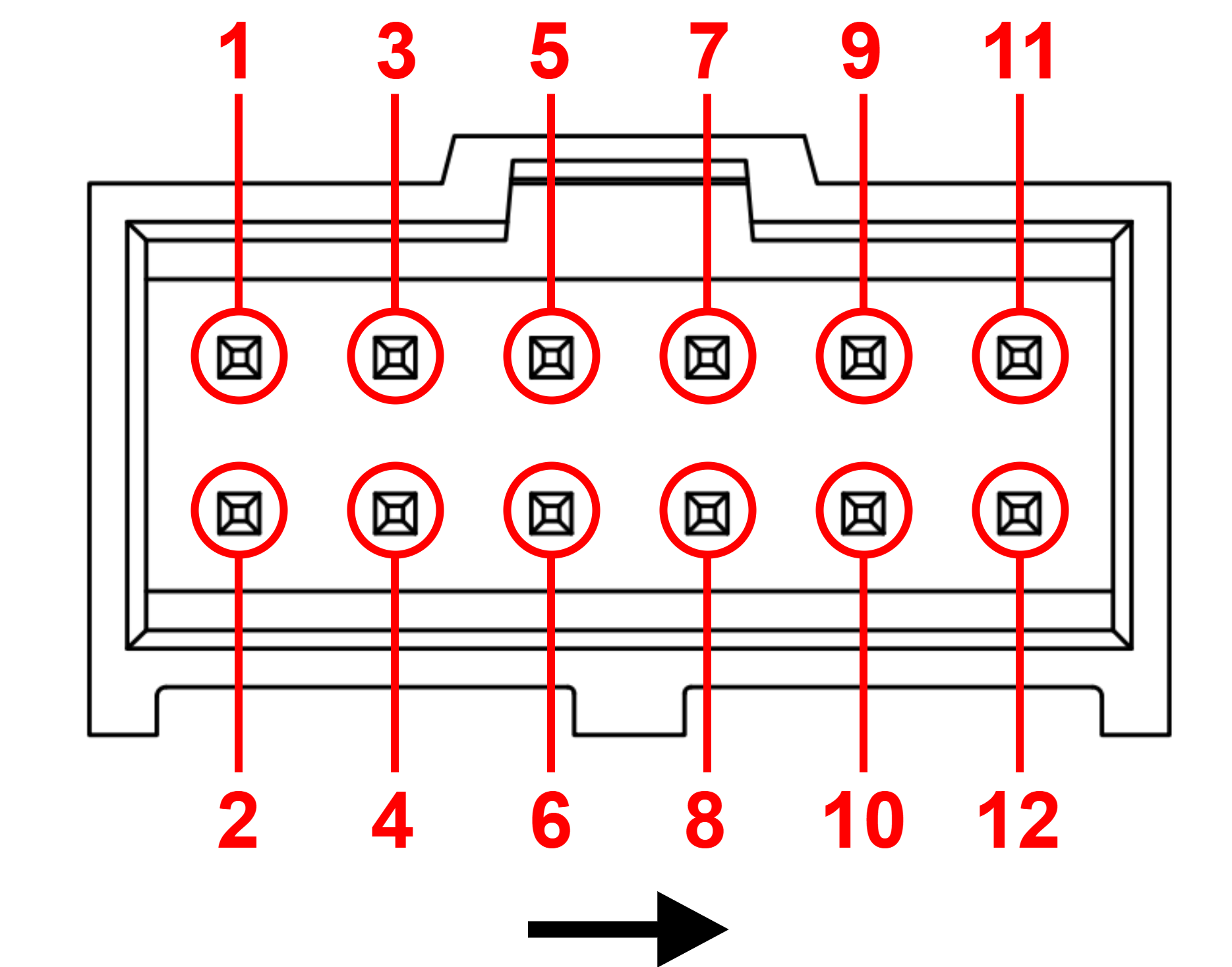
| PIN | Signal | Description | PIN | Signal | Description |
|---|---|---|---|---|---|
| 1 | ENC_SIN | Sine input from encoder | 2 | ENC_COS | Cosine input from encoder |
| 3 | GND_ISO | Isolated ground | 4 | 5_V_HALL | Isolated 5 V |
| 5 | ENC_A * | Encoder A | 6 | ||
| 7 | ENC_B * | Encoder B | 8 | ENC_Z * | Encoder Z |
| 9 | GND_ISO | Isolated ground | 10 | ISO_TEMP | External temperature sensor measurement |
| 11 | 12 | 1_V | Power supply for external temperature sensor (1 V) |
Note
* : These inputs are digital, incremental and optocoupled inside MC110.
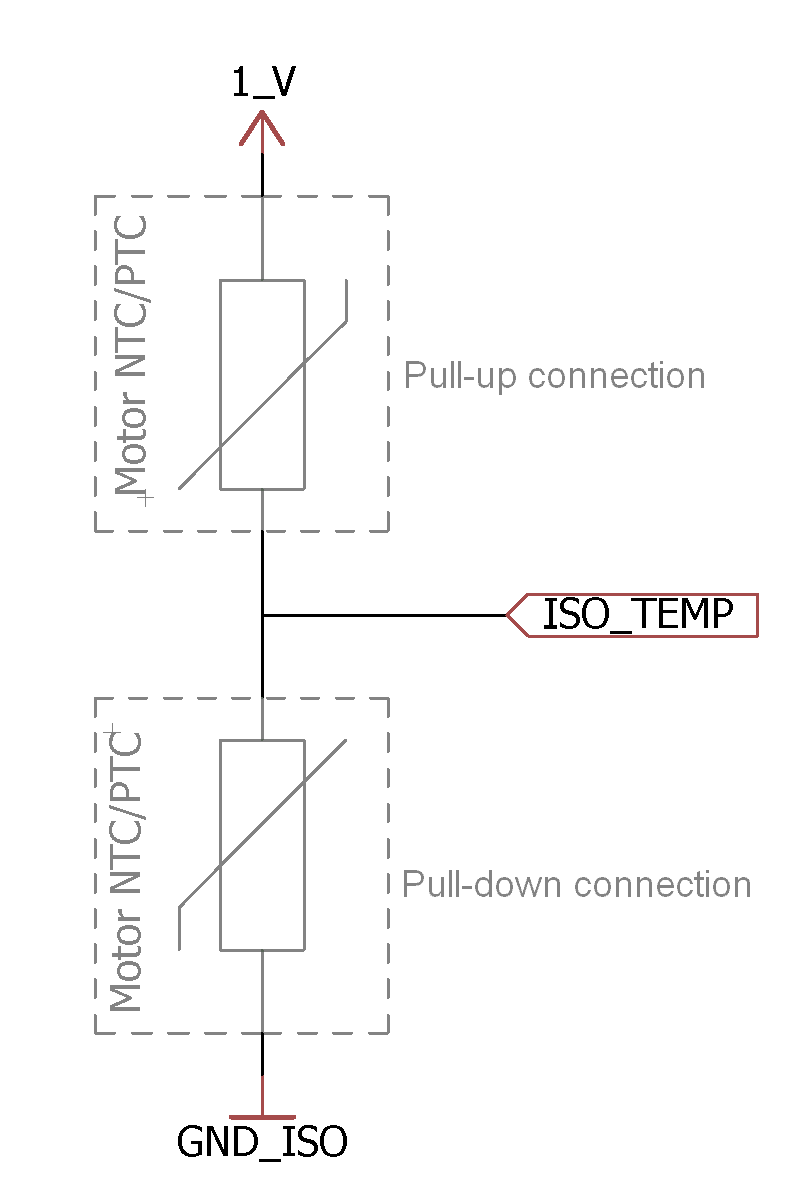
Important
-
If the temperature sensor is connected as a pull-up resistor, pin
1_V(12) will be the voltage reference. -
If the temperature sensor is connected as a pull-down resistor, pin
GND_ISO(3, 9 or 11) will be the voltage reference.
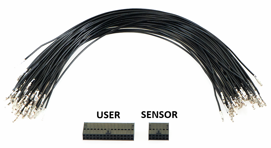
Harnesses
A wire harness is a structured assembly of cables and connectors used to organize and manage wiring in electrical and electronic systems. It is designed to ensure a tidy and secure installation of cables, preventing tangles, electromagnetic interference, and facilitating maintenance.
| Dev Harness MC110 2.0 for User Connector |
Conn Harness MC110 2.0 | |
| User Connector Harness | Sensor Connector Harness | |
|
|
|
| Harness available on demand with the Embention reference P008503 | Harness available on demand with the Embention reference P008609 | |
Dimensions
- Dev Harness MC110 2.0 wire gauge: 22-24 AWG
- Cables length: 30 cm
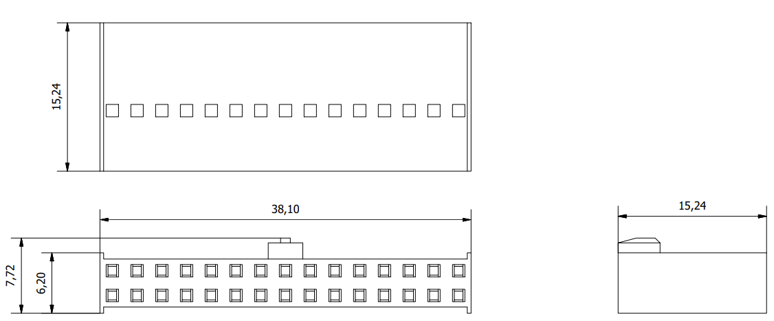
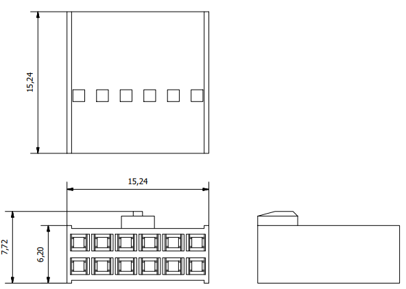
- Harness plug dimensions:
Pinout
Conn Harness MC110 2.0
- The pinout of the Conn Harness MC110 2.0 - User Connector is the same as the User Connector pinout above.
- The pinout of the Conn Harness MC110 2.0 - Sensor Connector is the same as the Sensor Connector pinout above.
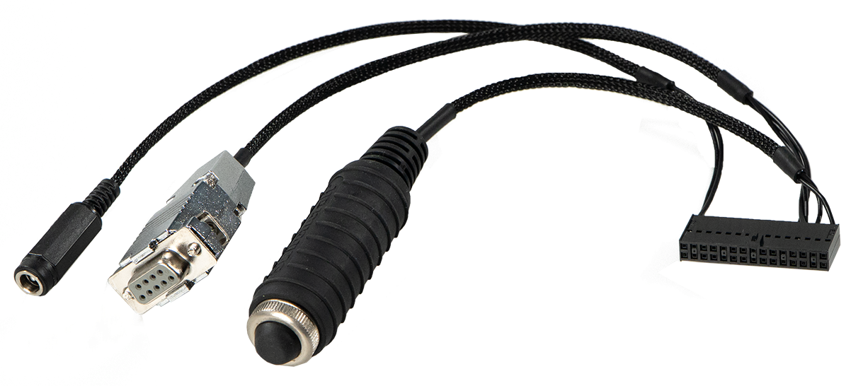
Dev Harness MC110 2.0
The pinout of this harness is the same as the User Connector pinout above. In addition, this harness has some connectors already implemented for easy operation. Below is detailed information on which pins these connectors are connected to:
| Connector | PIN | Signal |
|---|---|---|
| Main VCC | 30 | VCC |
| 29 | GND | |
| RS232 connector | 8 | RS232_TX |
| 10 | RS232_RX | |
| 7 | GND | |
| Maintenance button | 2 | HRBT_IN |
| 6 | SYNC_IN |
How to Turn On and Off
Note
Grounding: The MC110 uses two separate ground circuits to prevent interference: One for the low voltage supply and another for the high voltage supply. It is vital that these circuits remain isolated. Optionally, the equipment enclosure can be connected to the chassis for added safety and protection.
MC110 has two electric circuits: control (1) and power (2).
To turn on the voltage supply (with devices such as switches, relays or MOSFETs), it is mandatory to do it with the following order:
- Control circuit (1): User connector.
- Power circuit (2): HV negative and HV positive cables.
The following figure illustrates the connection order:
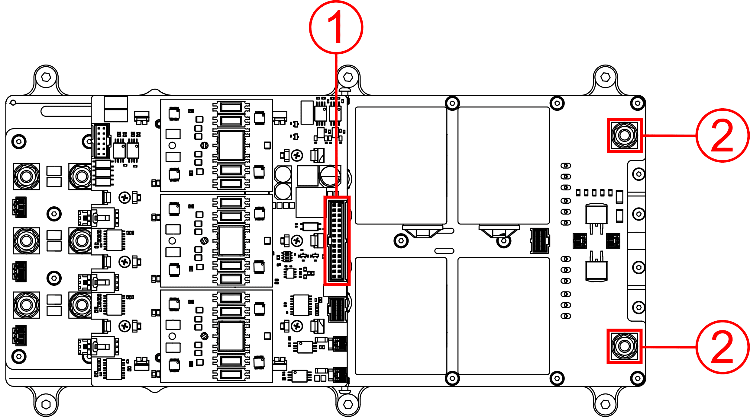
To turn off the MC110, reverse the order:
- Power circuit (2): HV negative and HV positive cables.
- Control circuit (1): User connector.
Electrical Diagram of CAN Bus
Like any other CAN device, Veronte MC110 requires a termination resistor to allow the connection of multiple MC110s or other CAN bus devices to the same line. For this termination resistor, users can add an external resistor or simply activate the 120 resistor that MC110 has internally (this is activated via software).
Below are some of the different configurations according to users preference.
Important
The scenarios described below are provided as examples of common setups. Users are free to implement custom wiring configurations that best suit their vehicle's design.
The critical principle for any valid setup is that the CAN bus line must be terminated with a 120 Ω resistor at its two physical ends: one at the beginning and one at the end. As long as this rule is followed, any combination of internal or external resistors may be used.
In this setup, the MC110's internal resistor is not used. Instead, two external 120 resistors are placed at the physical ends of the CAN bus to provide termination. The MC110 can be located anywhere on the bus, including at the end, but its internal resistor must remain disabled in the software.
This configuration uses the MC110's built-in termination feature for one end of the bus. The Veronte MC110 is placed at one physical end of the line, and its internal 120 resistor is enabled via software. A single external 120 resistor is then installed at the opposite end of the bus to complete the termination.
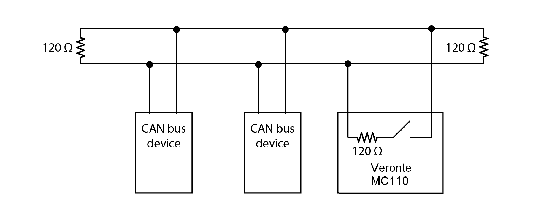
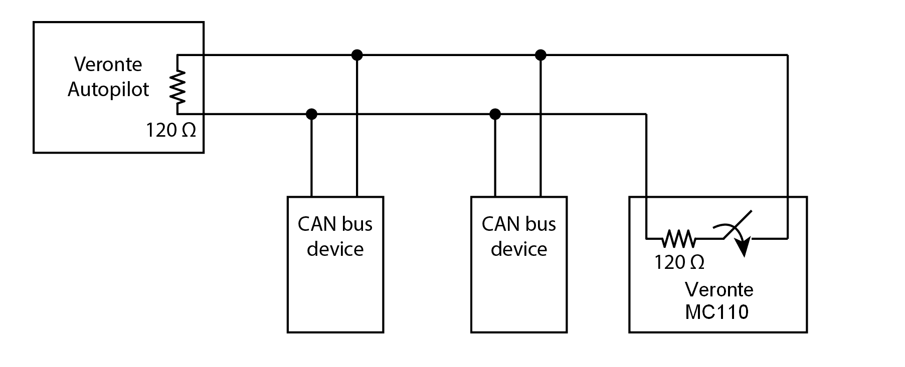
Considering Veronte Autopilot includes one entrance resistor of 120 , for the simplest wiring, this configuration uses the internal resistors of both the Veronte Autopilot and the Veronte MC110. The Veronte Autopilot, which includes a 120 resistor, is placed at one end of the bus. The Veronte MC110 is placed at the other end, and its internal 120 resistor is enabled via software. This setup provides full bus termination without requiring any external components.
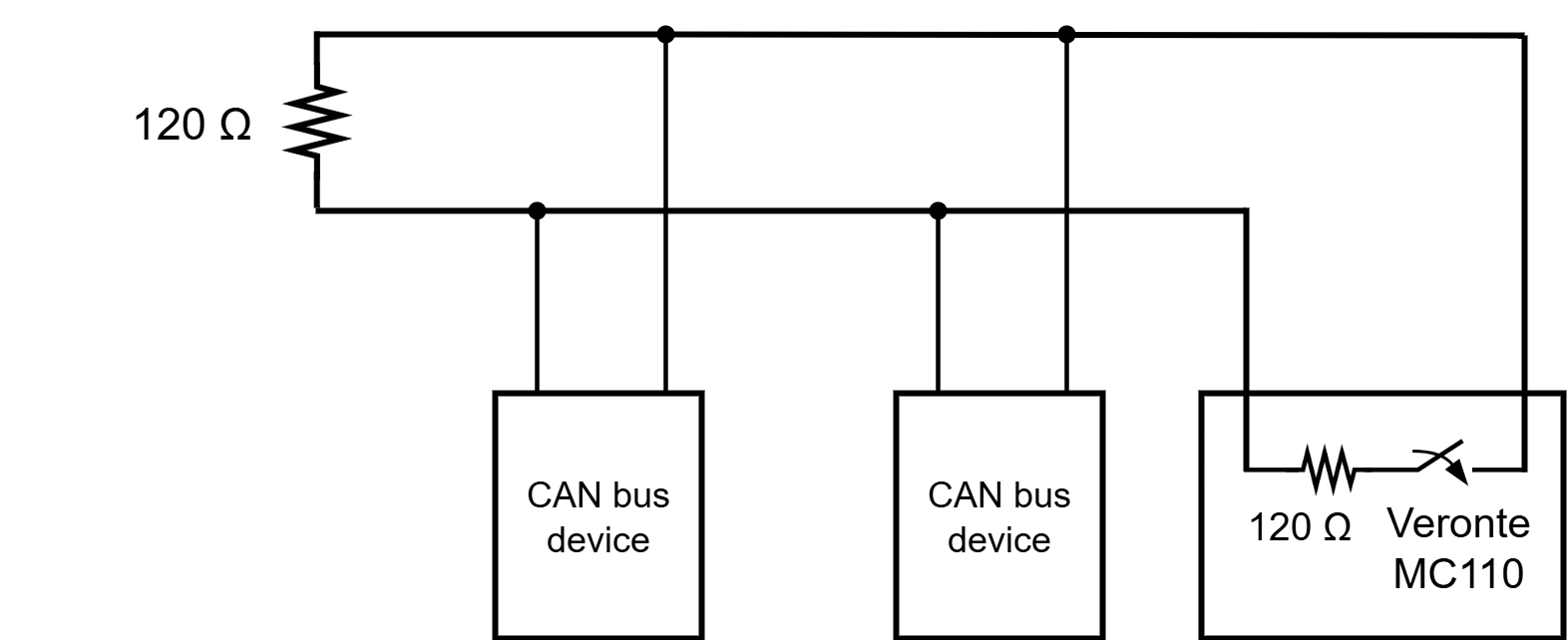
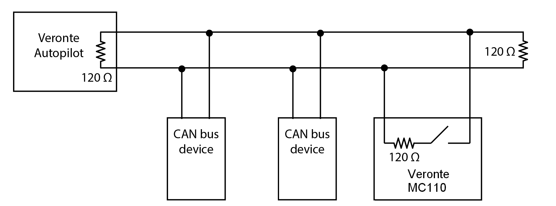
In this latter case, the 120 internal resistor of the Veronte Autopilot is placed at one end of the bus and an external 120 resistor is installed at the end of the CAN bus, leaving the internal resistor of the Veronte MC110 disabled, as shown in below:
Note
To enable or disable the resistor, refer to the Mailboxes - Input/Output section of MC110 PDI Builder user manual.
© 2025 Embention. All rights reserved.