Operation
In order to establish a connection between a Veronte device and a PC with Veronte Link, follow the steps:
-
Authentication is required before any operation.

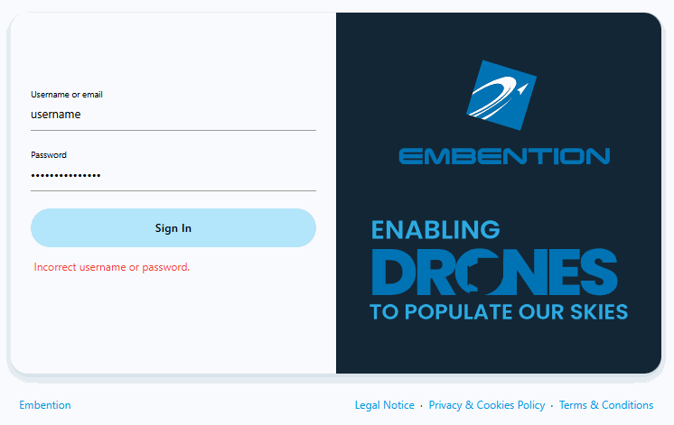
Veronte Link - Login After clicking Sign in, a new window will open for users to enter their credentials. If users do not have credentials, do not know what they are or have any problems logging in with them, please contact the support team via the Joint Collaboration Framework opening a Ticket or contact sales@embention.com.
If the login is successful, the screen will change as shown below:

Veronte Link - Login successful Warning
If incorrect credentials are entered, the system will display the error message Incorrect username or password.
Connect the device to a PC via Serial (USB, RS232 or RS485) or UDP/TCP (Wifi or Ethernet).

Note
Connecting the device to the PC is not necessary when communicating via Veronte Cloud. Please, see Cloud connection for further information.
-
Open Veronte Link, then a similar image to the following should be displayed:

Veronte Link interface - Devices menu - Veronte Link version: Informs the user about the version of the software being used.
- Devices: This is the currently displayed menu. It shows the devices connected to the PC.
- Connections: This menu allows the user to configure the connection between the PC and a Veronte device. See Connections section for more information.
- Sessions: In this menu users can play back recorded logs and flights. See Sessions section for more information.
-
Cloud connection: This menu allows the user to configure the internet connection between the PC and the available Veronte Autopilots 1x.
See Cloud connection section for more information.
Note
Only available if the user has logged in.
-
Login: Log in to the desired account.
- Set disconnect timeouts: Configure a timeout after which the autopilot is disconnected if Veronte Link receives no data.
- Find all: Runs a discovery to all devices.
- Search from ID: Searches for a specific device by its ID. Entering the ID 999 will search for all devices.
- Unique autopilot ID: Autopilot UUID.
-
Refresh configurables: It is recommended to use in case of any connection error.
Note
Only available if a device is connected or has been connected.
-
Remove device: Only works after disconnecting the device.
Note
Only available if a device is connected or has been connected.
-
Veronte device: Here it is displayed an image of the Veronte device that is connected.
- Dark/light mode: Switches to light/dark mode, changing the display mode of the interface.
- Terms and Conditions: Users can consult the 'End User License Agreement (EULA)' by simply clicking on this button.
- Port: Port through which the autopilot is connected.
- Hardware version
- ID: Autopilot ID.
- Software version
- Unit: Can be 1x or 4x.
-
Configuration status: It can be:
- PDIF: Waiting to read
- PDIF: Reading
- PDIF: Ready
- PDIF: Failed load
- PDIF: Not Downloaded (for products other than Veronte Autopilot 1x)
- PDIF: Not compatible
Note
Products are typically operational even if the configuration is not marked as "ready".
-
Device status: Can be in Normal mode, Maintenance mode or Loaded with errors.
- Connection status: It can be Connected or Disconnected.
- Serial number: Expressed in hexadecimal.
Important
Once Veronte Link is executed, an icon will appear in the taskbar and a browser window will open.

To close the application, it is not enough to close the browser window, it is necessary to right-click on the icon and select Close.
If the browser window is closed, it can be accessed again by pressing the Open button.
Connections
-
UDP Multicas Configuration: Verontelink manages the bidirectional communication between a device and a STANAG CUCS via UDP multicast. It transmits messages from the device to the configured destination IP/port and forwards incoming messages received on the dedicated receiving port back to the device.

UDP Multicast Congifuration menu - IP Adress: The multicast group address to which the data is sent and received.
- Sending Port: The local UDP source port used for sending messages to the multicast group
- Recelving Port: The dedicated UDP port used by the application to listen for incoming messages and forward them to the device.
- Time to Live: Time To Live, it is the maximum amount of time or 'hops' that a UDP packet can exist inside a network before being discarded by a router. A default value should automatically be set.
- Network interface: This setting defines the device's network adapter used by Verontelink for multicast traffic. You can choose a specific interface or let the operating system manage the routing (System default).
To implement the changes, it is necessary to restart Veronte Link after saving the configuration.
In this menu users must configure the connection type of the Veronte device.

Clicking on the ![]() icon will display the configuration panel. The parameters to be configured depend on the type of connection selected:
icon will display the configuration panel. The parameters to be configured depend on the type of connection selected:
Warning
Apart from Type and Port parameters, it is not recommended to modify the default configuration, as the default parameters should work correctly.
-
Serial: USB, RS232 or RS485 connections.

Serial connection configuration -
Port: Select the port of the computer to which the device is connected. It does not have to be the same as the one in the example image (Veronte Link interface).
More information about the port where the device is connected is explained in Serial connection - Integration examples section of the present manual.
-
Baudrate: This field specifies how fast data is sent over a serial line.
-
Parity: Is a method of detecting errors in transmission.
When parity is used with a serial port, an extra data bit is sent with each data character, arranged so that the number of 1 bits in each character, including the parity bit.
The available options are EVEN, MARK, ODD, SPACE and NONE.
-
Flow control: RTS/CTS and XON/XOFF control can be configured if needed.
- Data bits: Defines the number of bits in the message. It can be configured from 5 to 8 bits.
- Stop bits: Number of stop bits sent at the end of every character. Can be 1, 1.5 or 2.
- Advanced:
- Reconnect time: The time to consider a device reconnected. Default is set to 5 seconds.
- Disconnect time: Time to consider a device disconnected is defined here. 1 second is configured by default.
Note
In case of not getting the device connected, make sure that the PC acquires a communication port.
-
-
UDP: Ethernet or Wifi connections.

UDP connection configuration Important
Consider the maximum packet size supported by the Veronte Communication Protocol (VCP) when using serial data converters.
- Address: IP address, normally set to 239.0.0.1 (for broadcast) or 127.0.0.1 (for local).
- Port: IP Port must be set.
-
TTL: Time To Live, it is the maximum amount of time or 'hops' that a UDP packet can exist inside a network before being discarded by a router.
A default value should automatically be set.
-
Buffer size: Users would have to increase or decrease this value depending on the number of devices sending information through this channel.
By default this parameter has a value of 300, which is the maximum value of a VCP message.
Explanation
For example, if a PCS is connected by radio to an Autopilot 1x, the buffer size should be increased because more consecutive messages arrive and can be mixed between them, generating invalid messages that cause messages to be discarded.
Note
How to establish a connection via UDP is detailed in the UDP connection - Integration examples section of the present manual.
-
TCP-SERVER: Ethernet or Wifi connections.

TCP-SERVER connection configuration - Port: Set the TCP port from which the devices will get the information provided by Veronte Link.
-
Buffer size: Users would have to increase or decrease this value depending on the number of devices sending information through this channel.
By default this parameter has a value of 300, which is the maximum value of a VCP message.
Explanation
For example, if a PCS is connected by radio to an Autopilot 1x, the buffer size should be increased because more consecutive messages arrive and can be mixed between them, generating invalid messages that cause messages to be discarded.
Otherwise, if a very high buffer size is set, and only one device sends messages, the buffer will take longer to fill up, thus generating a delay in the reception of messages.
Note
How to establish a TCP-SERVER connection is detailed in the TCP-SERVER connection - Integration examples section of this manual.
-
TCP-CLIENT: Ethernet or Wifi connections.

TCP-SERVER connection configuration - Address: Enter the address of the device from which Veronte Link has to obtain the information.
- Port: Enter the TCP port from which the information is obtained.
-
Buffer size: Users would have to increase or decrease this value depending on the number of devices sending information through this channel.
By default this parameter has a value of 300, which is the maximum value of a VCP message.
Explanation
For example, if a PCS is connected by radio to an Autopilot 1x, the buffer size should be increased because more consecutive messages arrive and can be mixed between them, generating invalid messages that cause messages to be discarded.
Note
How to establish a TCP-CLIENT connection is detailed in the TCP-CLIENT connection - Integration examples section of this manual.
Finally, click on Save.
Sessions
Sessions tab displays all finished device sessions.
Important
- Sessions that are currently being recorded will not be displayed.
- A session from the currently connected device cannot be replayed.
- If users experience problems when attempting to replay a session, please check the Error when replaying a session - Troubleshooting section of this manual.
Each block represents the autopilot session.

The following images describe each functionality.

Devices: The user can select one or more devices they want. Click the All button to select all devices.

Range: This function allows the user to enter the time range they want to examine.
- Enter a date range: Enter the start and end dates of the session.
- Start time: Enter the session start time.
- End time: Enter the session end time.
The display shows the entered data:

- Date and time of session start.
- Date and time of the moment being displayed.
- Date and time of session end.
Hovering over the session block displays the following:

- The start date and time of the session.
- The and date and time of the session.
- The duration of the session.
- The autopilot version.
- The file weight.

- Stop: It stops playing the session. It does not delete the session.
- Play/Pause: The button allows you to pause or resume the session.
- Rewind/forward: Enables rewind or forward by thirty seconds.
- Speed: Playing speed can be selected as x0.5, x1, x2, x4 and x8.
Cloud connection
Cloud connection tab allows the user to connect to a Veronte Autopilot 1x through LTE network. This functionality is enabled thanks to the HSPA+ module (internal or external) embedded in Veronte autopilots.
Note
To activate the internal card or Veronte Cloud data traffic through internet, please contact sales@embention.com. Remember that there is no internet connection when HSPA+ module is deactivated.
To configure this type of connection, these steps must be followed:
Warning
In order to set up and operate a Veronte Autopilot 1x via Cloud connection, users must first:
-
Log in Cloud.
-
Establish a connection to Autopilot 1x that is not through Cloud (Serial, UDP, TCP-Server or TCP-Client).
-
Upload PDIF (configuration) to 1x with the 1x PDI builder app or with the Upload PDIFs to cloud button
 .
.This button will work as long as the cloud device is connected and the PDIFs are in the Ready state otherwise it will show errors:

Now the users are ready to establish the connection via Cloud and work. If these steps are not followed, Autopilot 1x will be in PDIF: Failed load status.
Note
This only needs to be done once per Veronte Autopilot 1x and per configuration. > Login credentials are automatically assigned. In case they have not been provided to you, please contact the support team by creating a ticket in the customer's Joint Collaboration Framework; for more information, see Tickets section of the JCF manual or contact sales@embention.com.
-
Open Cloud connection tab. Veronte Autopilots 1x linked to user's account should be displayed.

Cloud Connection: Available devices The following information is displayed for each autopilot:
- ID: Identification number of the autopilot (Serial Number).
- Last connection: Indicates the date on which the last connection to that device was established.
-
Activate the connection with the desired Autopilot 1x by turning on the toggle button displayed next to it.

Cloud Connection: Connect to an Autopilot 1x Note
Since Cloud connections are based on LTE communication, this connection may not be immediate. The selected autopilot will only be displayed in the 'Devices' tab when it is succesfully connected.
-
At this point, Veronte Link must have established the connection with the selected Autopilot 1x. Consequently, the autopilot must be displayed in the Devices tab.
Note
Since Cloud connections are based on LTE communication, connection may be lost even when the toggle button is on. In this case, the autopilot will disappear from the 'Devices' tab, appearing again when the connection is retrieved.
To log out, click on the username to enable the log out button, and then press it.

© 2026 Embention. All rights reserved.