Servo Configuration
The T-Rex integration process can be performed by using Veronte Pipe connected with the hardware system and the Autopilot as explained in section Aircraft Mounting of the manual.
Servos Output
The first step of the process is the servos configuration. In this section will be explained how to set the servo-output matrix.
In this case, the controls of the helicopter are the cyclic, collective, RPM (main rotor) and blades pitch angle changing (tail rotor). To control the main rotor moving it is necessary to configure correctly the three servos that allow controlling the blades pitch angle and the one which changes the main rotor RPMs. In order to have the tail rotor control and to be able to change the blades pitch, another servo must be configured.
All the servos correspond to a pin of the connector and they must be positioned in the S vector who represents the Actuator Outputs. It is possible to connect any pin to any command but the easiest way to perform it and avoid confusion is by following the pins number.
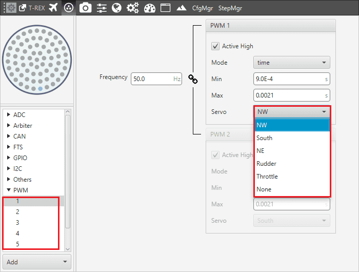
T-Rex Outputs
In this case, it is necessary to use 5 pins:
Output 1 – NW main rotor cyclic/collective
Output 2 – South main rotor cyclic/collective
Output 3 – NE main rotor cyclic/collective
Output 4 – Main rotor RPMs
Output 5 – Tail rotor blades angle changing
SU Matrix
At this point, the S vector is defined and the SU matrix can be edited. By clicking on Edit it is possible to configure the relation between the controller outputs (U vector) and the servo movements (S vector).
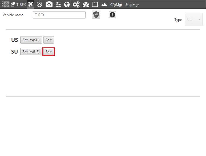
SU matrix edit
Warning
This panel shows the reference system of the aircraft too. It must be positioned in the same way of the Autopilot’s one. If it results different, it can be edited by clicking on the corresponding axis in order to reverse its direction.
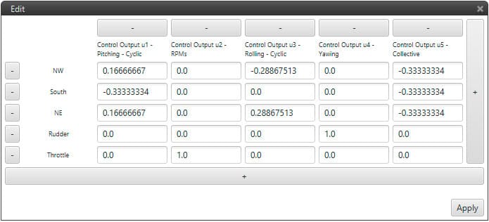
SU matrix
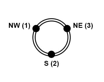
T-Rex swashplate actuators
The previous image shows the swashplate of the T-Rex with the 3 actuators able to modify its rotation plane (X axis is positive up). As showed in the SU matrix image, controls are performed as follow:
Pitch Angle Control: Control Output 1 is configured to perform a positive pitch angle change when servos 1-3 move following Z axis positive and servo 2 moves in the opposite direction with double magnitude.
RPM Control (Main rotor): the Control Output 2 (servo number 5) is the one that allows an RPM change with the throttle moving (0-1).
Roll Angle Control: Control Output 3 is configured to perform a positive roll angle change when servos 1-3 move with an opposite direction (servo 2 is in the longitudinal plane of the aircraft, so it has not any influence).
Yaw Angle Control: Control Output 4 is configured to perform a positive yaw angle change when tail rotor decreases the blades pitch angle.
Collective Control: The altitude control is performed using the Control Output 5. A positive change of the pitch angle blade is performed when servos 1-2-3 move contemporaneously in the same direction.
System Trim
As a final step, the system has to be trimmed. This can be performed by moving servos in three different positions: zero position, minimum and maximum (blade angles are usually limited physically). These positions must be inserted and saved in the software by clicking on Set when the actuator is in the desired position or introducing them manually.
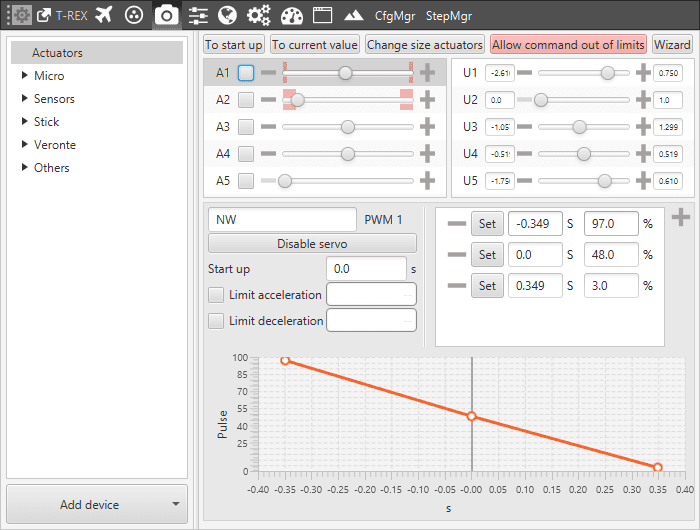
Actuator 1 trimming
This procedure can be performed in the same way by using a Wizard. This tool allows moving actuators limits easily and finding the correct range.
.jpg)
Trim wizard tool
In order to perform a final checking, it is possible to select the desired channel and testing pitching, rolling, yawing and thrusting controls.
The image below shows a pitching output testing. By moving the U1 control (Pitching – Cyclic), main rotor servos change the position according to the reference system: positive corresponds to nose down and negative to nose up.
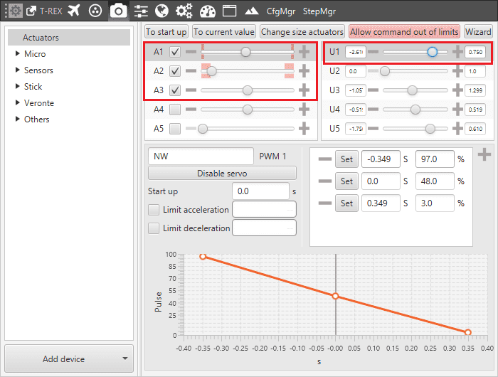
Pitching test
