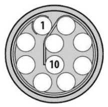
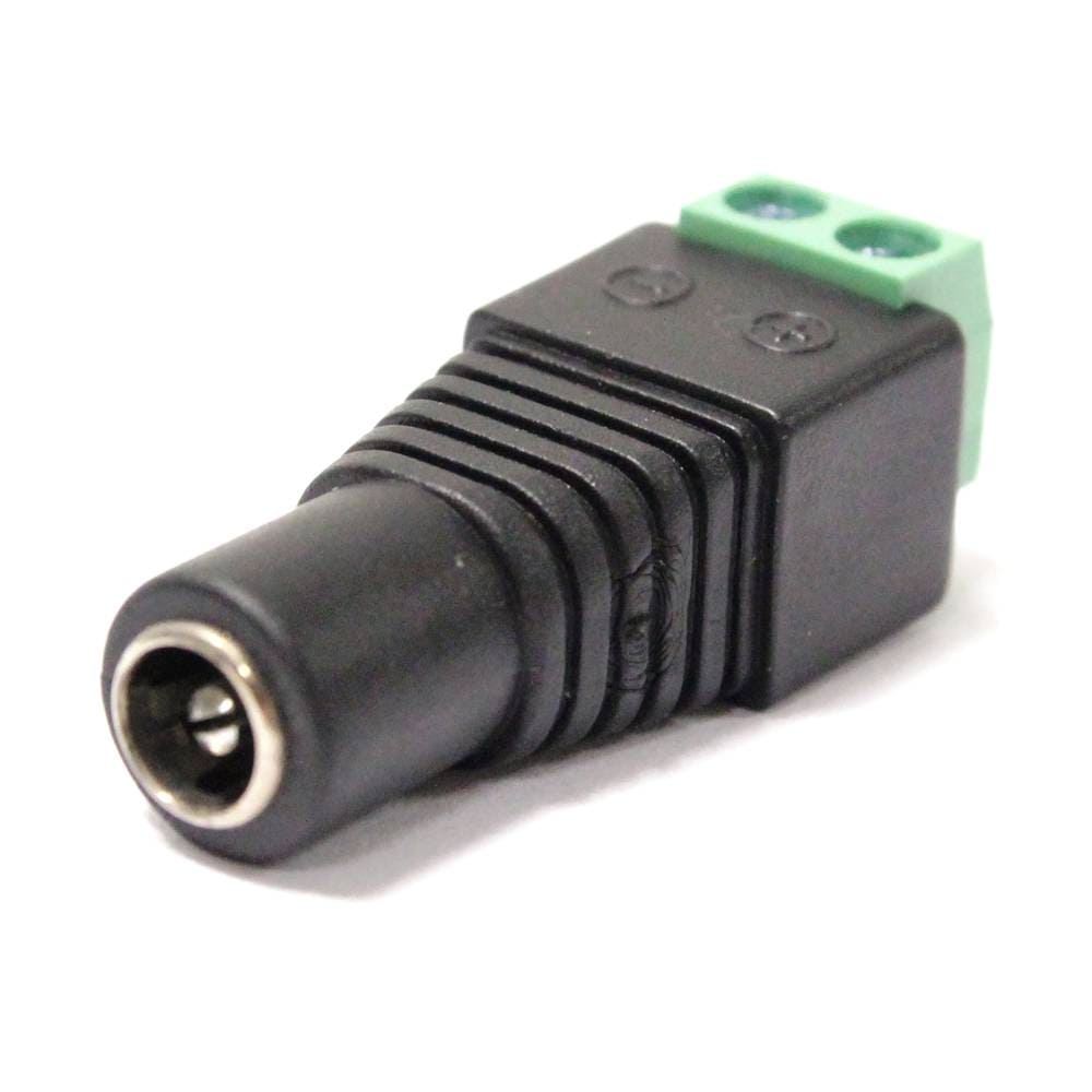
A wiring configuration of the PRI cable connected to the PRI port of the radio is required in order to connect to the power supply, ethernet and RS-232.
When looking at the rotary multi position switch from the top, pull the knob towards you while rotating the knob towards the 1 position. This turns radio on. LED indicator will turn to fix red.
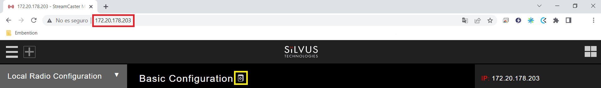
In order to access the StreamScape graphical user interface (GUI), connect Ethernet (RJ45) connector of PRI cable to Ethernet port of laptop/computer.
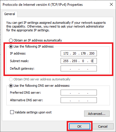
Make sure computer is set to static IP address on same subnet as radio.
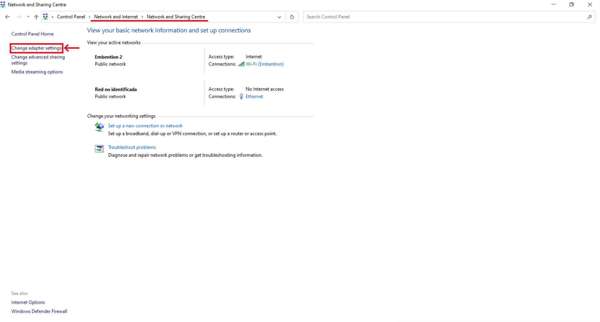
Open network and sharing menu and click change adapter settings.
Once the website has been accessed, follow the steps below which show the parameters that need to be modified for correct operation and pairing of the radios.
Note
This is an example of the radio configuration linked to a Veronte air unit.
Note
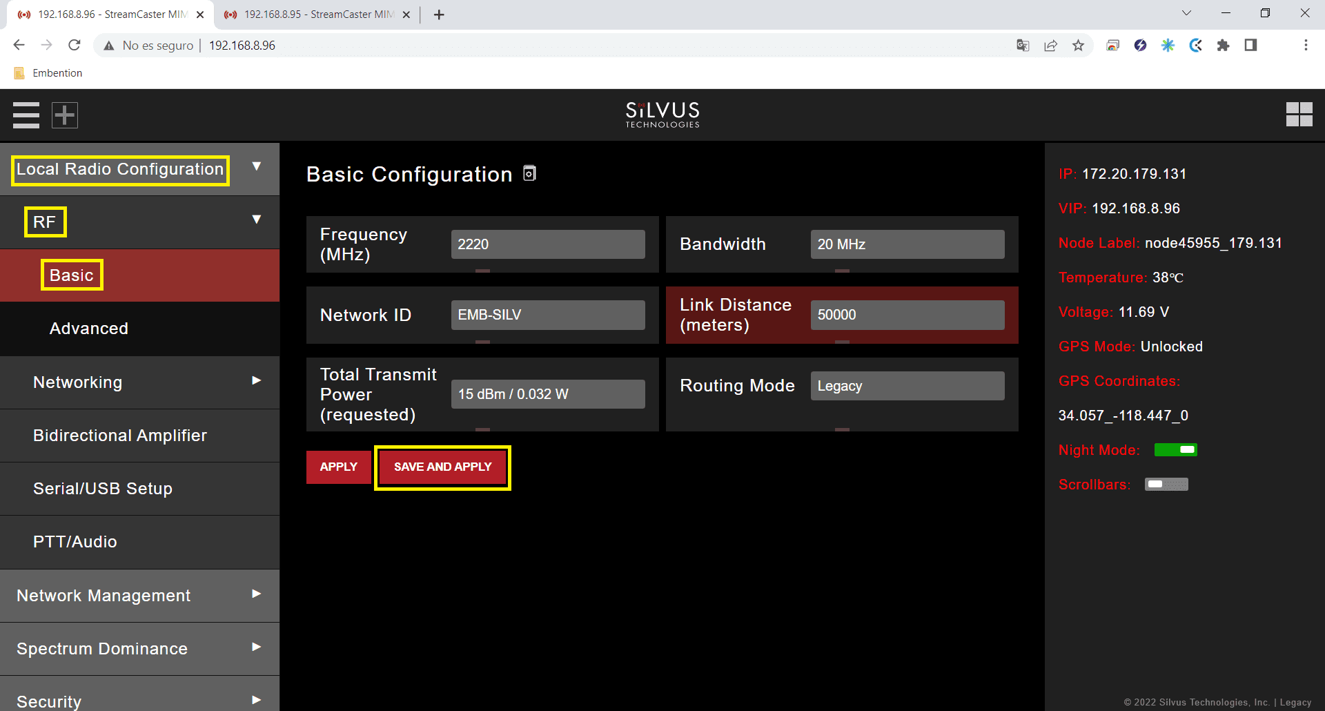
After making changes to each window, it is important to click on “Save and apply”.
Frequency (MHZ): This defines the frequency of the signal. There is a drop-down menu for frequency selection. We recommend 2220 MHz.
Warning
Be careful when choosing the frequency. The user may see interference with the Wifi frequency band, consult the radio spectrum.
Bandwith: This defines the RF bandwidth of the signal. Default value.
Network ID: Network ID allows for clusters of radios to operate in the same channel, but remain independent. A radio with a given Network ID will only communicate with other radios with the same Network ID.
Link Distance (meters): Set to an approximate maximum distance between any two nodes in meters. It is important to set the link distance to allow enough time for packets to propagate over the air. It is recommended to set the link distance 10-15% greater than the actual maximum distance.
Total Transmit Power (requested): This defines the total power of the signal (power is divided equally between the radio antenna ports). Set the appropriate power for each application. The power that has been set is small, as it is sufficient for our tests.
Routing Mode: As Large Network mode requires a license and is not available outside USA, we set Legacy mode.
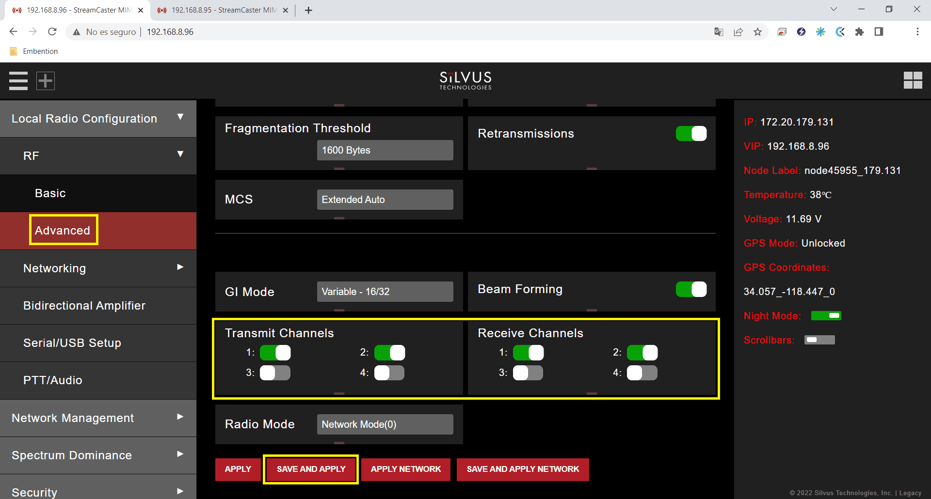
Transmit/Receive Channels: Allows user to Enable or Disable each channel on the radio for TX/RX (each RF port is a channel). We have enabled both channels.
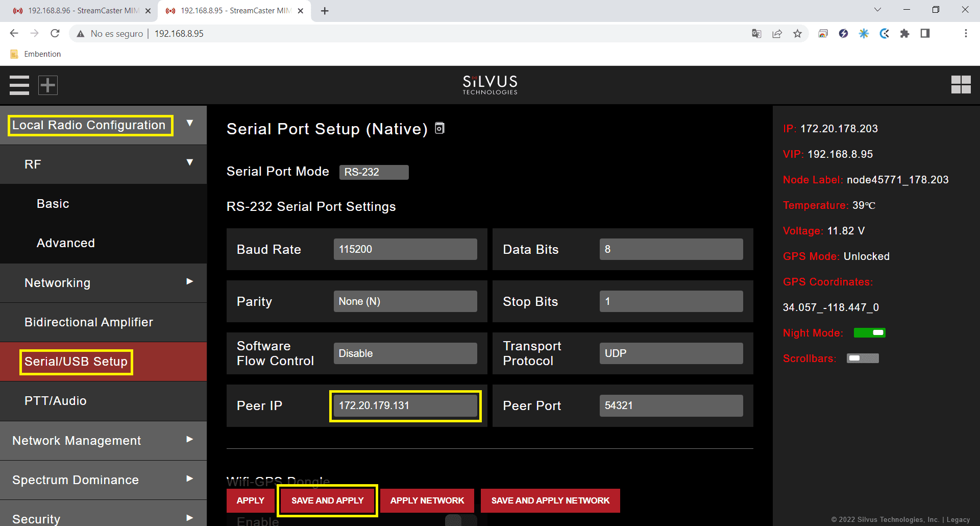
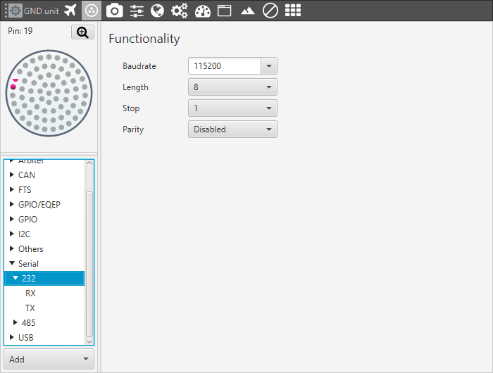
The value of the Baudrate, Data Bits, Parity and Stop Bits parameters must be the same as those configured in Veronte Pipe.
Software Flow Control: Disable.
Transport Protocol: We recommend UDP. If no data loss can be tolerated, change this setting to TCP on the radio corresponding to the Veronte air unit.
Peer IP: This should be the IP address of the radio on the other end of the RS-232. In this example, we must set the IP address of the radio linked to the GND unit.
Note
Both radios (the one connected to the GND unit and the one connected to the AIR unit) have the same configuration except for the Peer IP.
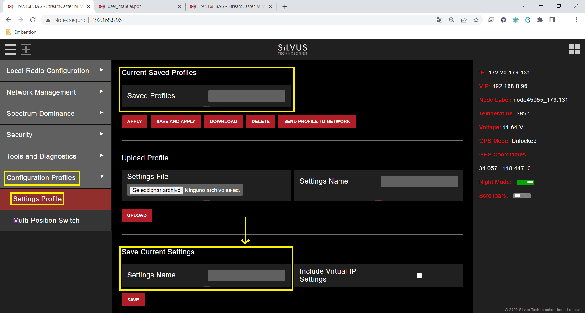
In addition to these settings, different configurations can be stored in the same radio, on the Multi-Position Switch panel. The user can select the one that will work, with the radio’s switch position.
In this example only one configuration has been created.
With the above settings the configuration is finished. Furthermore, this configuration can be saved and downloaded in the Settings Profile window of the Configuration Profiles section.
After configuring both radios with these settings they should be paired. Therefore, if we connect them to the power supply, when we switch them on, the LED will turn from fix red to fix green, this indicates that it is connected to at least one radio. Also, if we connect only one of them to the computer, we can access the StreamScape GUI of both of them.
And, in the Network Topology window of the Network Management section, we can see the link between them.