Hardware Installation
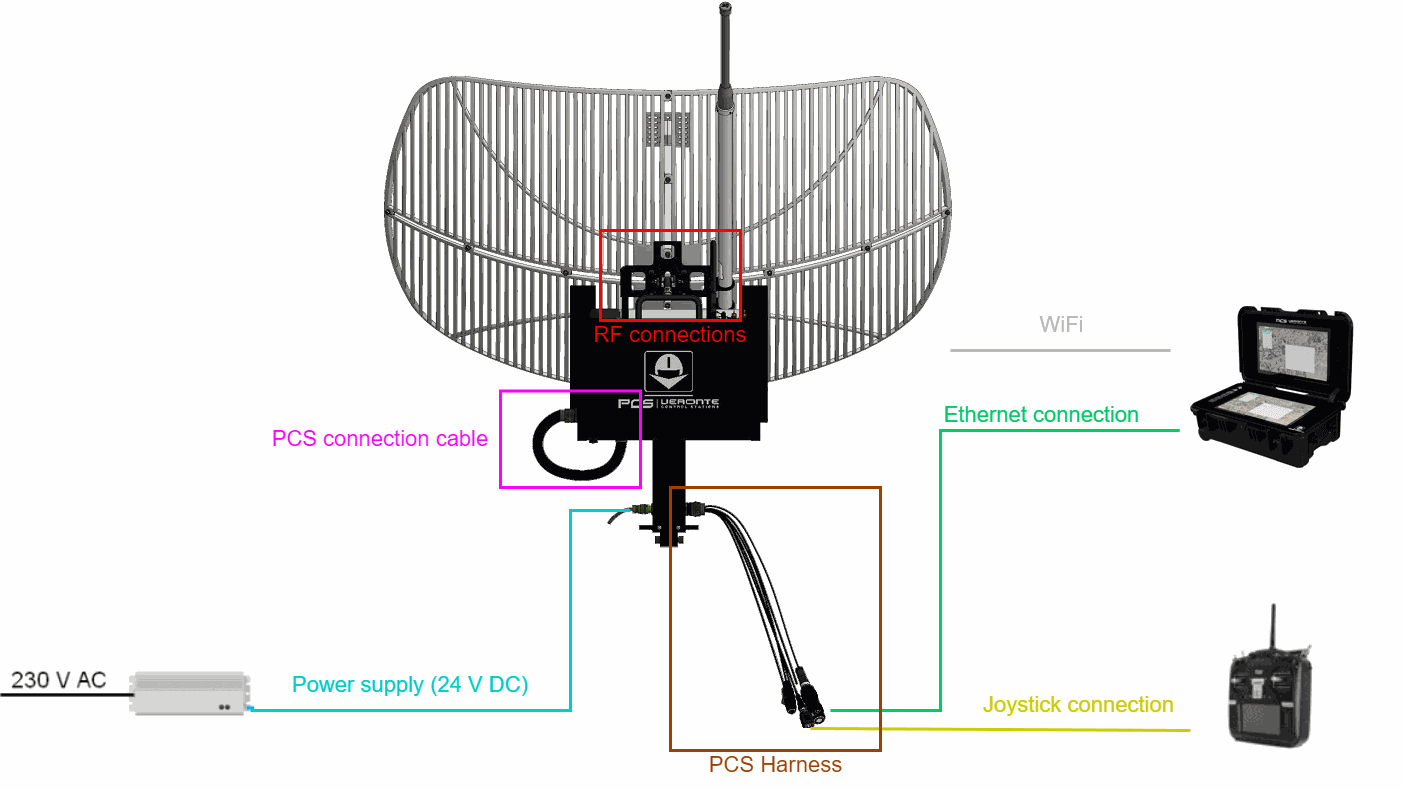
Basic Connection Diagram
Pinout
PCS Harness
The PCS pinout can be read in the section Pinout - Hardware Installation of the PCS user manual. (remember to select the product version on the webpage). Nonetheless, the following pins of PCS should not be used when a T28 is connected, since they have not internal connections:
| NOT USED PINS | |||
|---|---|---|---|
| 5 | I/O5 | 58 | EQEP_I |
| 6 | I/O6 | 60 | RS485_B_TX_P |
| 7 | I/O7 | 61 | RS485_B_TX_N |
| 27 | 24V_OUT | 62 | RS485_B_RX_N |
| 42 | FTS1_OUT | 63 | RS485_B_RX_P |
| 43 | FTS2_OUT | 65 | GND |
| 44 | 12V_OUT | 66 | |
| 48 | VCC | 67 | VCC |
| 55 | 12V_OUT | 68 | |
| 56 | 24V_OUT | ||
Since power supply is disabled in the harness connector, it is established with the power connector.
Warning
Compatible only with PCS harness. Do not attach other type of harness, please contact Embention before doing it.
Warning
CAN A Interface has a two configurable termination resistor. If other elements are connected to CAN A Bus this termination resistor should be disabled. CAN B and CAN FD only have one configurable termination resistor. We recommend to use CAN B and CAN FD for customer implementation and CAN A for internal purposes, although CAN A can also be used for customer implementations.
Important
CAN A has now an internal configurable resistor controlled with the GPIO signal (Pin 58 from PCS). It is ON by default so the CAN A is terminated with the 1xVeronte and the last VMC.
GPIO --> 0: CAN Termination disabled
GPIO --> 1: CAN Termination enabled
Power Connector
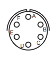
The connector installed in veronte T28 pole is the 71-533722-06P. Use PT06A-10-6S(005) as mating connector.
Next table describes the pinout of the power connector:
| Pin | Function |
|---|---|
| A | 24V |
| B | 24V |
| C | 24V |
| D | GND |
| E | GND |
| F | GND |
PAN-TILT Unit Installation
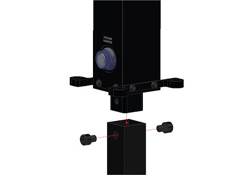
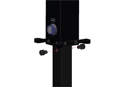
To install the PAN-TILT Unit on the Mast next steps shall be followed.
- Insert PAN-TILT Unit into the Mast and insert the two M10 screws.
- Fix two M10 screws with an 8 mm Allen wrench.
PCS Installation
Veronte PCS needs to have the Wall Mount accessory installed.
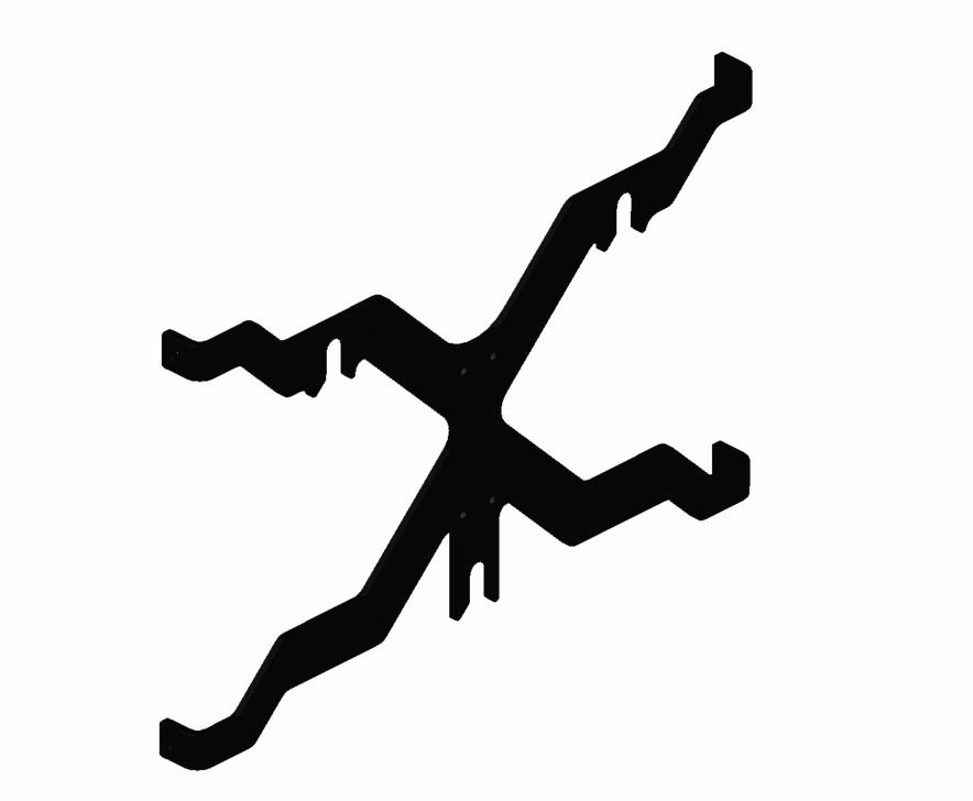
In the next picture hanging points are marked where Veronte PCS shall be installed.
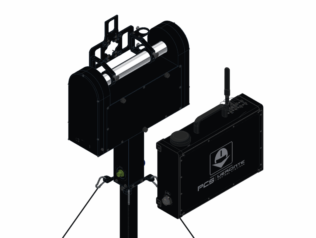
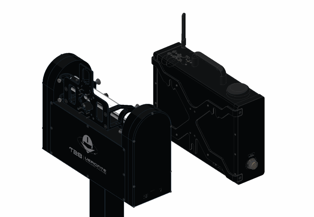
Slide the Veronte PCS to the three hanging points.
Mast Extension
To extend the mast, please follow next instructions.
- Loose the Mast fasteners.
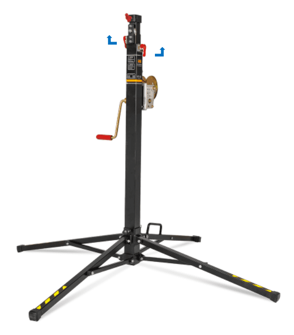
- Turn the crank to adjust the height.
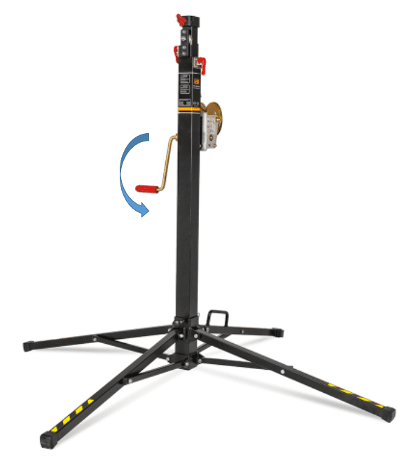
- Lock the Mast fasteners.
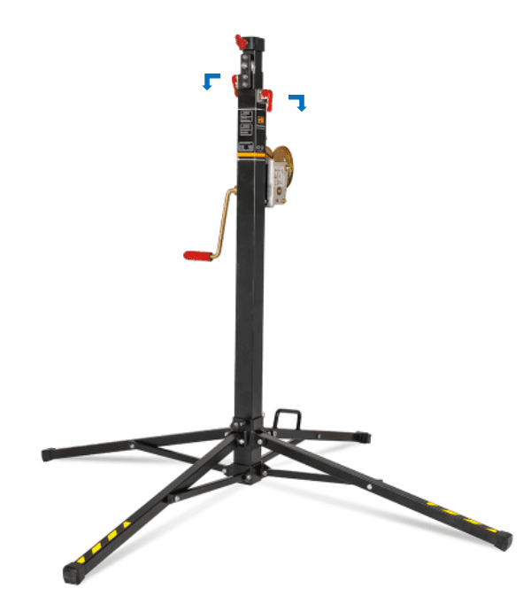
Guy Cable
Veronte T28 is supplied with 4 guy cables and 4 stakes to provide extra stability when mounted.
The use of the guy cables is mandatory when T28 rises more than 2.5 m although it is always recommended, even more in windy days.
- Attach the carabiners as shown in the picture.
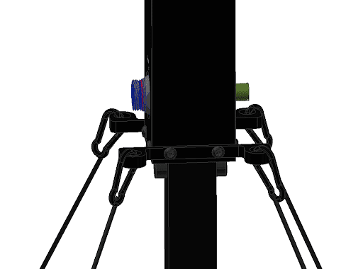
- Next picture defines the recommended distance between stakes.
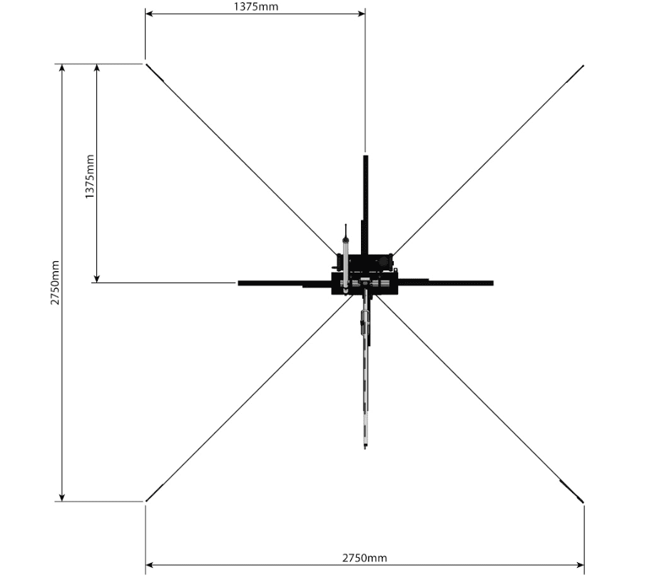
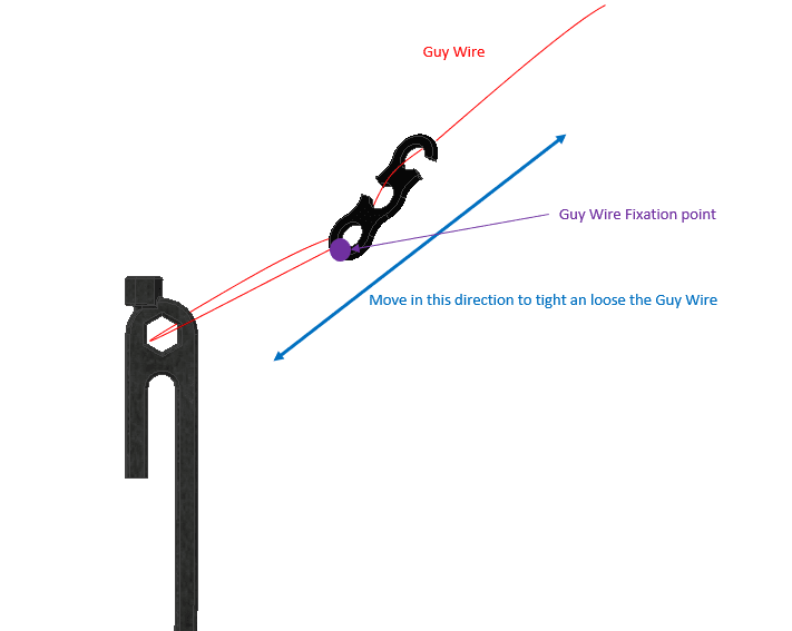
Once the stakes are installed, the guy cables need to be tightened.
- The next image illustrates how to tight and lose a guy cable.
© 2026 Embention. All rights reserved.