Quick Start
This user manual covers the assembly of Shifter. To use it, weld input and output wires according to the Pinout section.
The following diagram and table summarize the Shifter behaviour:
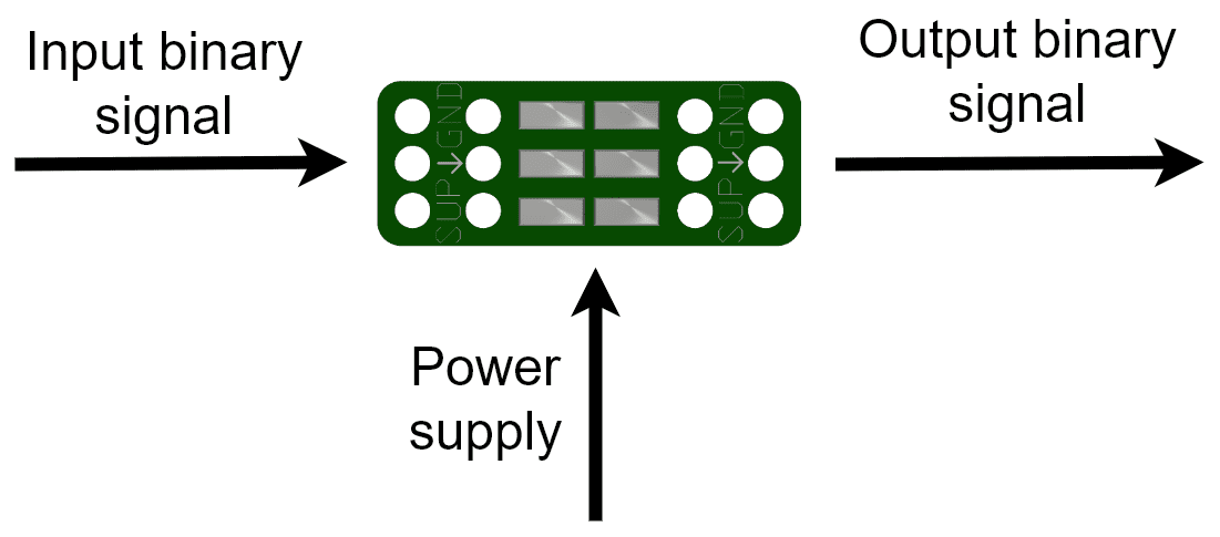
Input and output diagram
Case |
Result |
|---|---|
Input binary signal > 1.6 V |
Output binary signal = Power supply voltage |
Input binary signal < 1.6 V |
Output binary signal = 0 V (connected to ground) |
Warnings
Maximum voltage for input and power supply is 12 V.
Minimum voltage for the input signal is 1.6 V to be detected as high state.
Make sure Shifter is not thermally very insulated, to prevent overheating.
Be careful welding pads and avoid short-circuits between them.