Hardware Installation
Wiring
Each wire can be protected against pulling efforts. To do this, pass it throught its corresponding pair of holes and weld it to the pad.
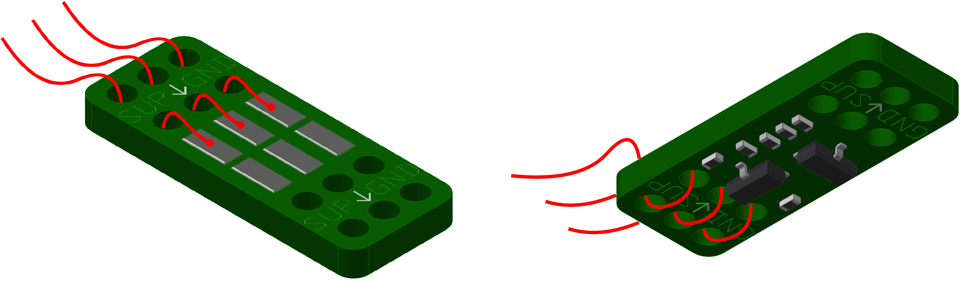
Wiring diagram
Pinout
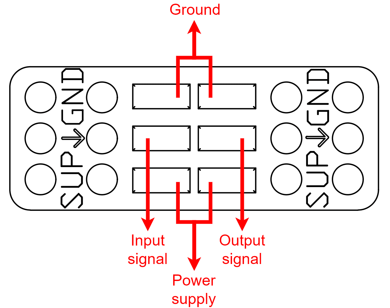
Pinout diagram
Notice that power supply and ground pads are duplicated. Each couple of pads are connected each other to allow a cascade connection.
Shifter has an open drain output with internal pull-up tied to power supply. So, when the input signal is on, the output pin is connected to the power supply through a 300 \(\Omega\) resistor; otherwise, it is connected to ground.
Cascade connection
It is possible to connect multiple Shifters in cascade, saving unnecessary wiring. The following image shows an example of 3 Shifters, each one using a different signal for its own device.
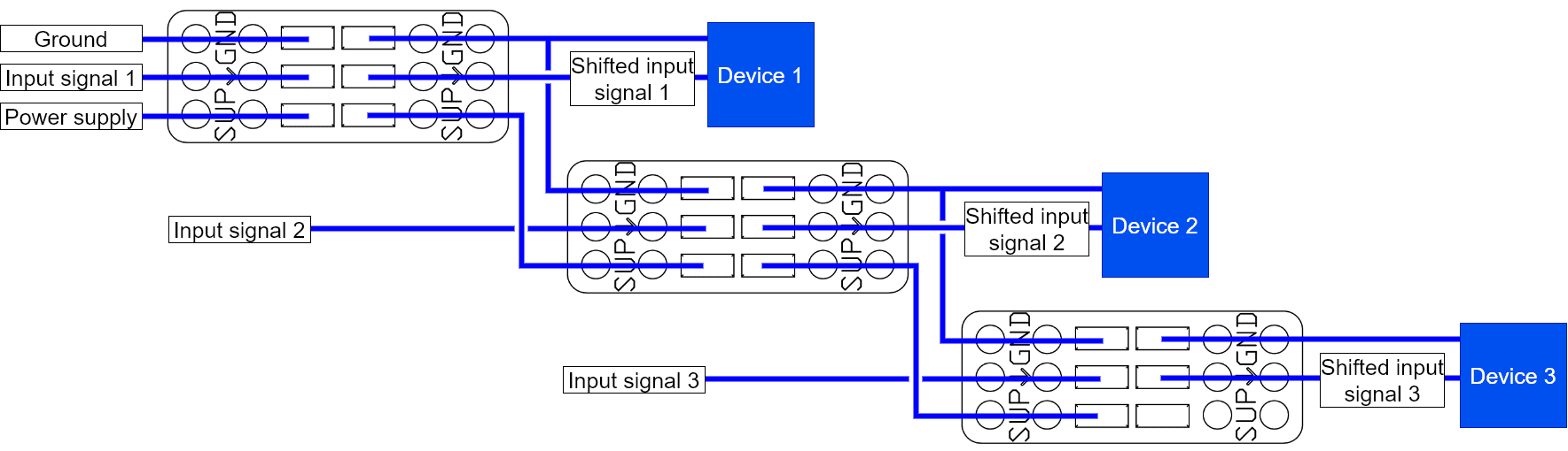
Cascade example diagram