Configuration
When SCI PDI Builder is executed, the following window and options will appear:
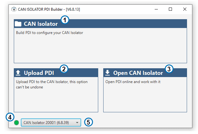
CAN ISO PDI Builder
Offline configuration: Click here to work with configurations offline, without the need of a connected device.
Upload PDI: Upload an existing configuration to the selected device. .. note:: PDI files are configuration files. This files are used by modular control with improved version management.
Open CAN Isolator: Open the configuration of the selected device.
Current mode: Current mode of the selected device. Click to alternate between Normal (Green) and Maintenance (Orange) modes.
Selected device: Selected device upon the connected devices.
Important
Builder and Firmware major and minor versions must match (For example, Firmware version 6.8.40 is compatible with Builder version 6.8.13, but not with version 6.10.13.
Clicking on 1. or 3. will open the configuration menu, where the following options are available:
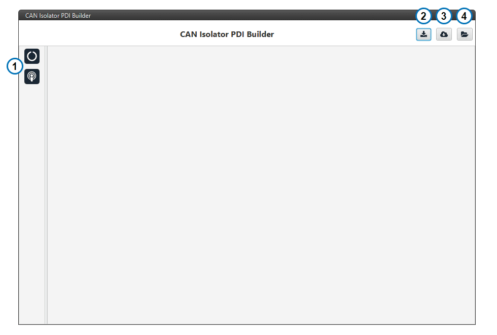
CAN ISO PDI Builder configuration
Configuration tabs: Access to the configuration of the different available features.
Export PDI: Save the current configuration files into your local storage.
Import Online PDI (NOT AVAILABLE YET): Import configuration from the available online configurations.
Import PDI from Local Storage: Import configuration from your local files.
Operating Modes
Smart CAN Isolator has two different operating modes. The current mode can be seen on the bottom left corner when connected to CAN ISO PDI Builder.
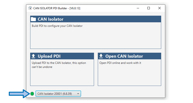
Smart CAN Isolator mode
Clicking on the indicator allows to switch the current mode.
Tip
Smart CAN Isolator will modify the baudrate of its interfaces when in maintenance mode. If these baudrates do not match your setup, an external configuration setup will be needed to modify the configuration.
With normal operating mode. The loaded configuration will be executed. Smart CAN Isolator will always try to boot in Normal mode.
Read Maintenance mode section to know more.
Establishing connection
The configuration of the Smart CAN Isolator can only be performed through one of its CAN interfaces.
In order to do this, a support device is needed to act as a configurator (for example a Veronte Autopilot or a Veronte CAN Expander).
Important
For configuration purposes, only specific baudrates can be used. Once in maintenance mode, 1M baudrate must be used to configure Smart CAN Isolator through the A interface, and 500k for the B interface. See Operating modes for more information.
CAN baudrate
1M for interface A, 500k for interface B:
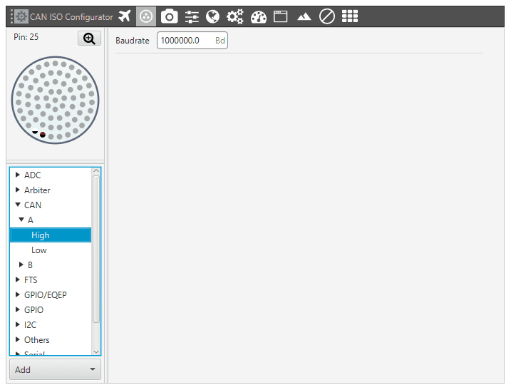
Port routing
Redirect the messages addressed to the Smart CAN Isolator through a Comm Manager port. For this example CAN Isolator S/N:20001 and Comm Port 6 are used:
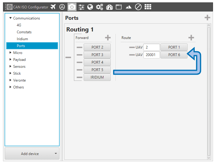
I/O Manager
In the I/O Manager, connect a Serial to CAN interface biderectionally with the selected Comm Manager Port:
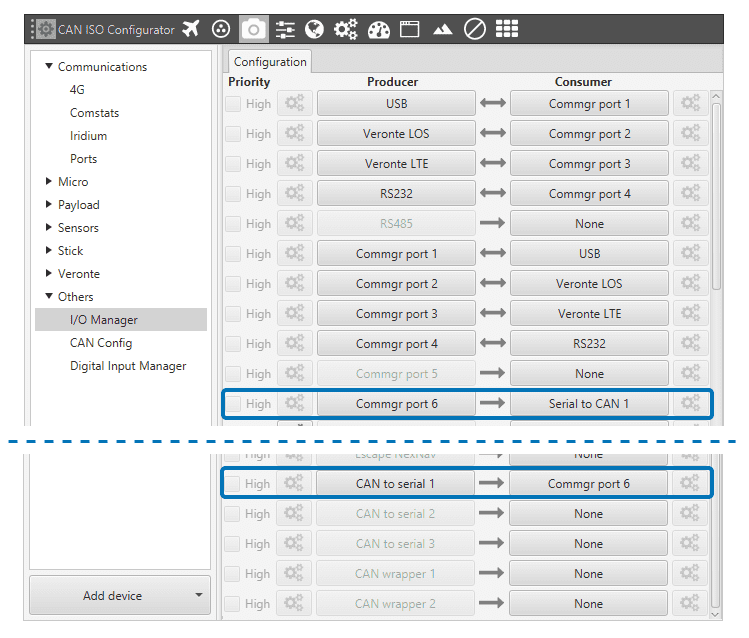
CAN Config
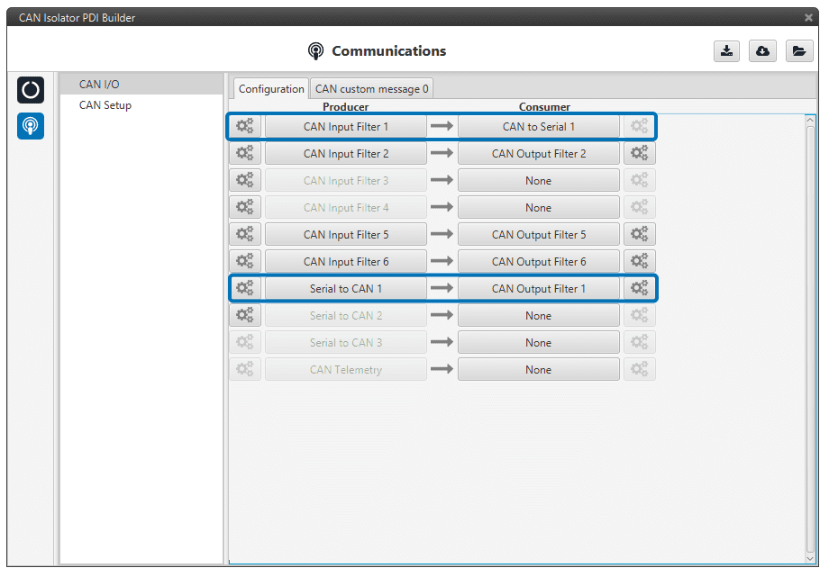
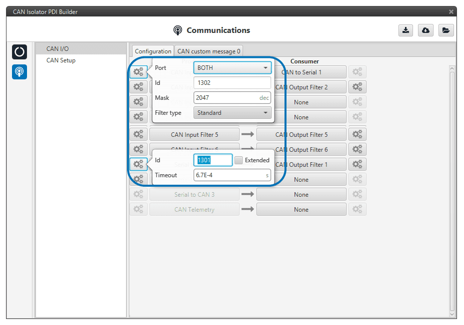
Connect the Serial to CAN and CAN to Serial producer and consumer to the respective input and output filters. Set both to High priority:
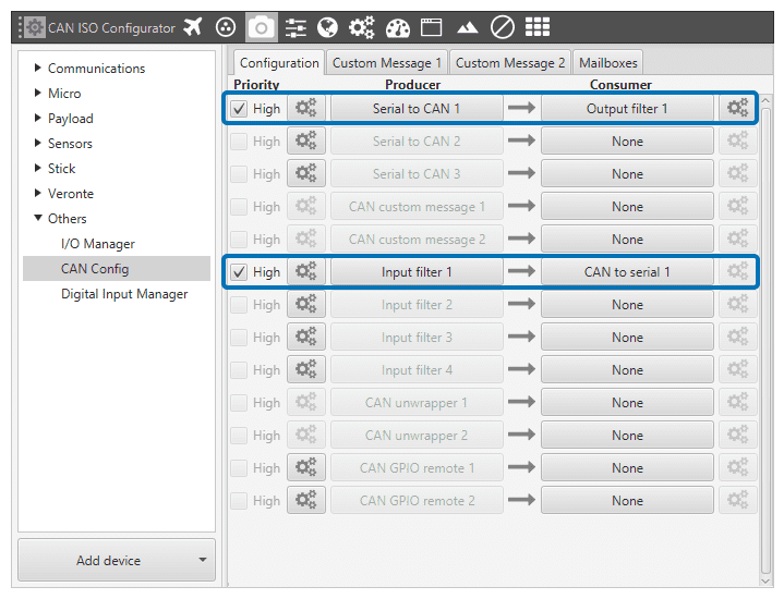
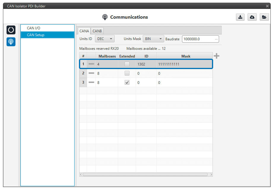
Use ID 1302 for Serial to CAN producer and ID 1301 for the Input Filter:
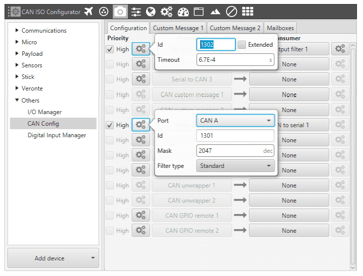
Finally, add CAN ID 1301 to the CAN Mailboxes
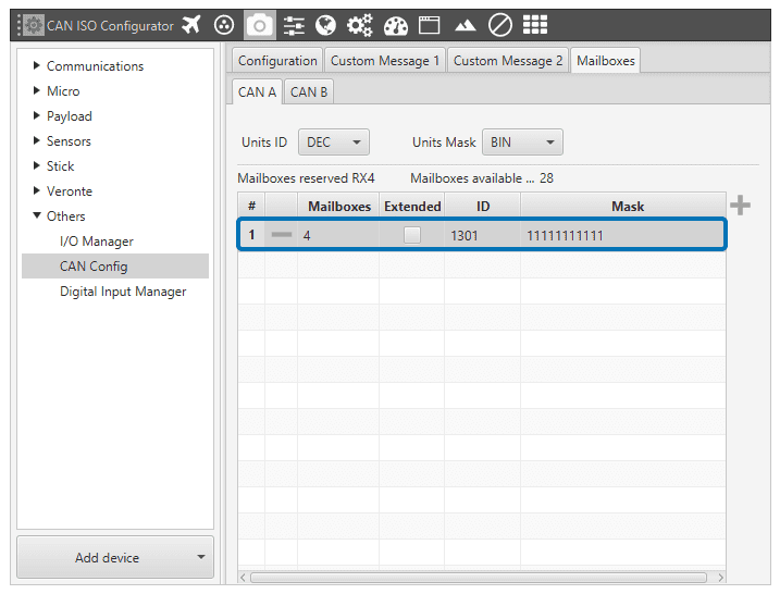
CAN configuration for normal mode
In order to be able to communicate with Smart CAN Isolator while in normal mode, a specific configuration is needed. This configuration will be set by default.
VCP
Enable VCP Status Message: (Veronte Communication Protocol) Smart CAN Isolator will send a periodic message so that other applications and devices in the Embention environment can know its status. The period of this message can be chosen, or it can be disabled of required.
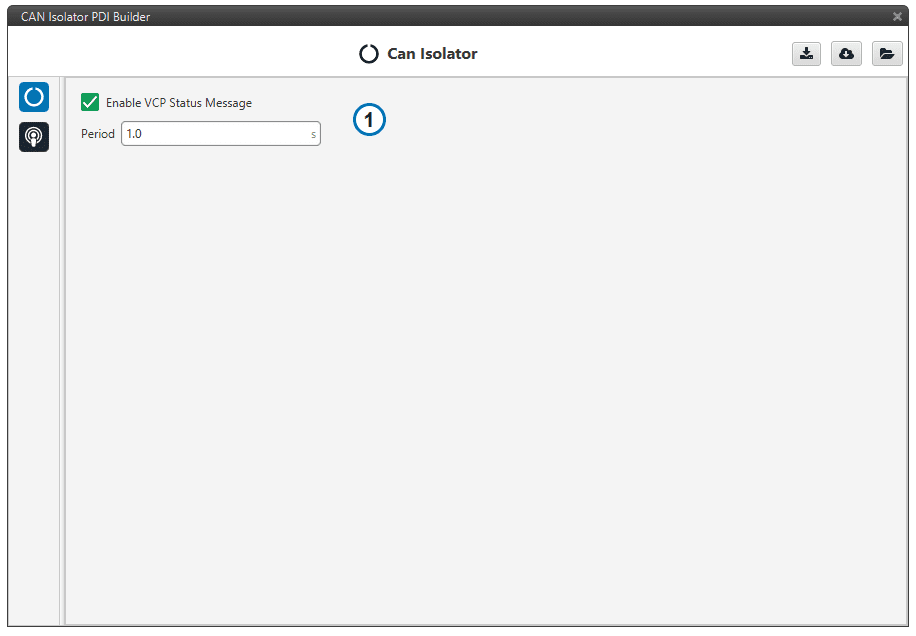
VCP Status configuration
Warning
Disabling the Status Message will disable other apps and devices from detecting Smart CAN Isolator automatically.
CAN I/O
Configuration of the CAN Producers and Consumers
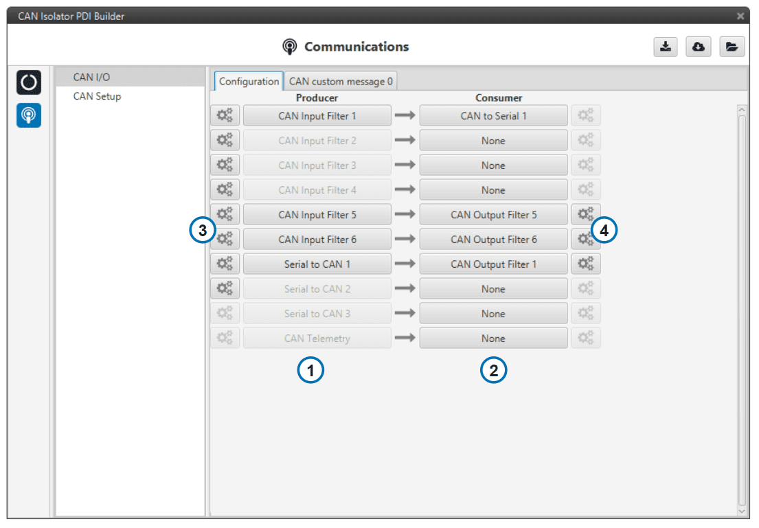
CAN I/O configuration
Producers: Producers allow to read CAN messages from the CAN buses or to create new ones.
Consumers: Consumers allow to process CAN messages or send them into one of the CAN buses.
Producer settings
Consumer settings
Producers
CAN Input Filter: Read CAN Messages from the CAN bus.
Important
For a message to be read by an Input filter, it must have an assigned mailbox in CAN Setup.
Serial to CAN: Producer for internal and configuration messages. Only Serial to CAN 1 is currently enabled.
CAN Telemetry: Custom CAN messages producers. See CAN Telemetry section.
Consumers
CAN Output Filter: Send CAN Messages into the CAN bus.
CAN to Serial: Consumer for internal and configuration messages. Only CAN to Serial 1 is currently enabled.
CAN GPIO consumer: Consumer for GPIO command messages. For controlling Smart CAN Isolator GPIO outputs, it is necessary to send activation for Virtual GPIO 02 (Interface A) and Virtual GPIO 04 (Interface B).
CAN Telemetry
With CAN Telemetry the user can create CAN custom messages using its internal variables. Examples of internal variables are:
Voltage Input
GPIO Status
Configuration CRC
Device ID
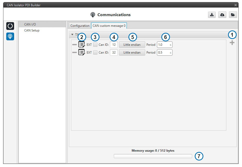
CAN Telemetry configuration
Add new CAN message: Add a new custom message to the CAN Telemetry
CAN Message Data: Edit the message Data field.
CAN ID Type: Select between Standard CAN ID (11-bit) or Extended CAN ID (29-bit).
CAN Message ID: CAN ID for the message.
Endianness: Big Endian, Little Endian or Hybrid.
Period: Frequency at which the message is sent.
Memory usage: Memory left for building CAN Telemetry messages.
CAN Setup
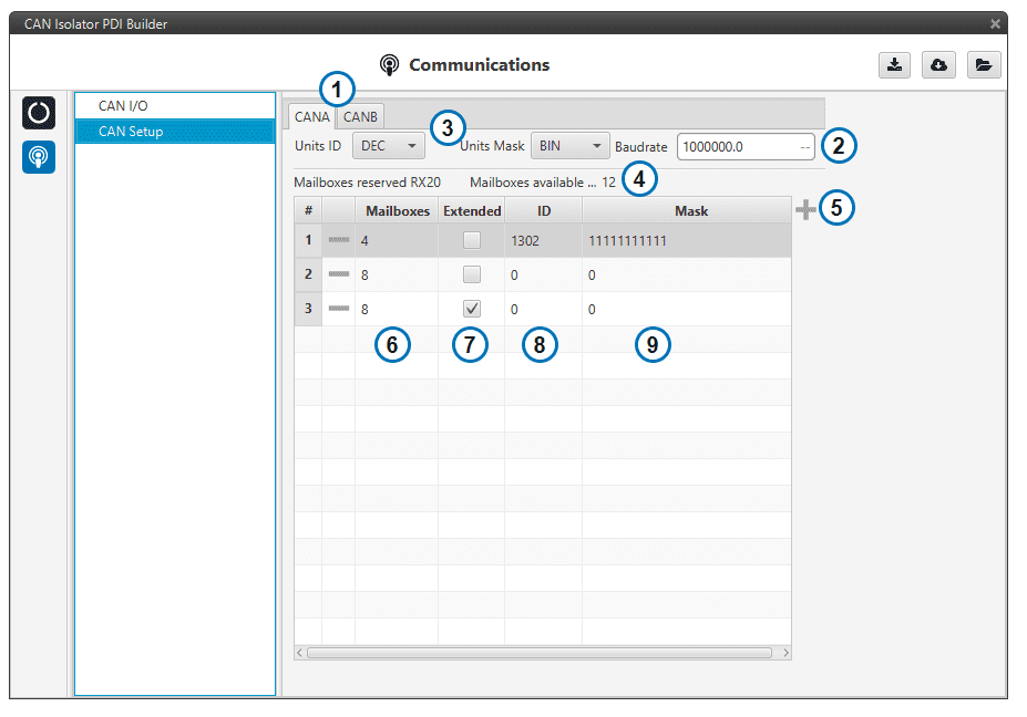
CAN Setup configuration
Interface selection: Apply settings to interface A or interface B.
Baudrate: CAN Baudrate for the selected interface.
Mask display settings: Select in which format the mask is displayed.
Available mailboxes: Current mailbox distribution.
Create new mailbox entry: Add a new line to the mailbox list.
Number of mailboxes: Number of mailboxes assigned to a given ID.
ID type: Select between Standard CAN ID (11-bit) or Extended CAN ID (29-bit).
ID: Input CAN ID.
Mask: Input mask. Use it for accepting more than one CAN ID within the same mailbox group.
Warning
At least one available mailbox must be left for Smart CAN Isolator to be able to send messages through that given interface.
