Technical
General description
Veronte REx is a flight control unit derived from the Veronte 4x. Its architecture includes three independent and dissimilar processors that manage the autopilot. Unlike the Veronte 4x, where the three internal processors are identical Veronte 1x units, in the REx each core has a specific role inside the autopilot: Primary, Monitor and Recovery.
- Primary: The main processing unit executing GNC commands.
- Monitor: Executing its own GNC, it checks system health and selects the core in control.
- Recovery: Takes control in case of failures, ensuring redundancy and safe operation.
Each Veronte Autopilot REx contains all the electronics and sensors needed to control the UAV, executing in real time the guidance, navigation and control (GNC) algorithms for the carrying airframe and processing the onboard sensor signals to command the propulsion and actuation systems.
Control diagrams
CAN bus
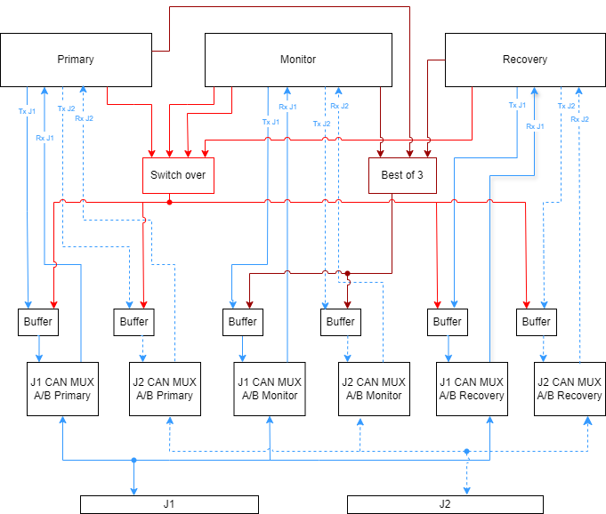
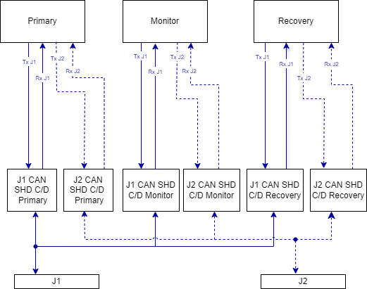
The Veronte Autopilot REx includes up to 8 CAN FD ports that can be configured as 8 independent buses or as 4 redundant channels. CAN A and B are multiplexed buses routed through J1 and J2. CAN C and D are shared buses routed through J1 and J2.
Multiplexed CAN A and B
By default, CAN A and B are multiplexed. This means that all three cores can receive CAN messages, but only one core can be in command. The Monitor manages the core in command through the Switch over block. When this mode is active, only the Primary or Recovery core can be in command.
These buses can be configured through the Best of 3 block to allow more than one core to transmit at the same time. Each core can be configured for one of the following modes:
- Primary and Recovery: Both the Primary and Recovery cores have Tx enabled at the same time.
- Primary, Recovery and Monitor: The Primary, Recovery and Monitor cores have Tx enabled at the same time. In this case, the bus operates as a standard shared bus.
To enable either mode, the Best of 3 logic requires at least two cores to have the corresponding mode enabled.
Shared CAN C and D
CAN C and D are fully shared buses. Each core connects directly to its own transceiver on J1 and J2, transmitting and receiving on the bus without arbitration or multiplexing.
RS232 and RS485
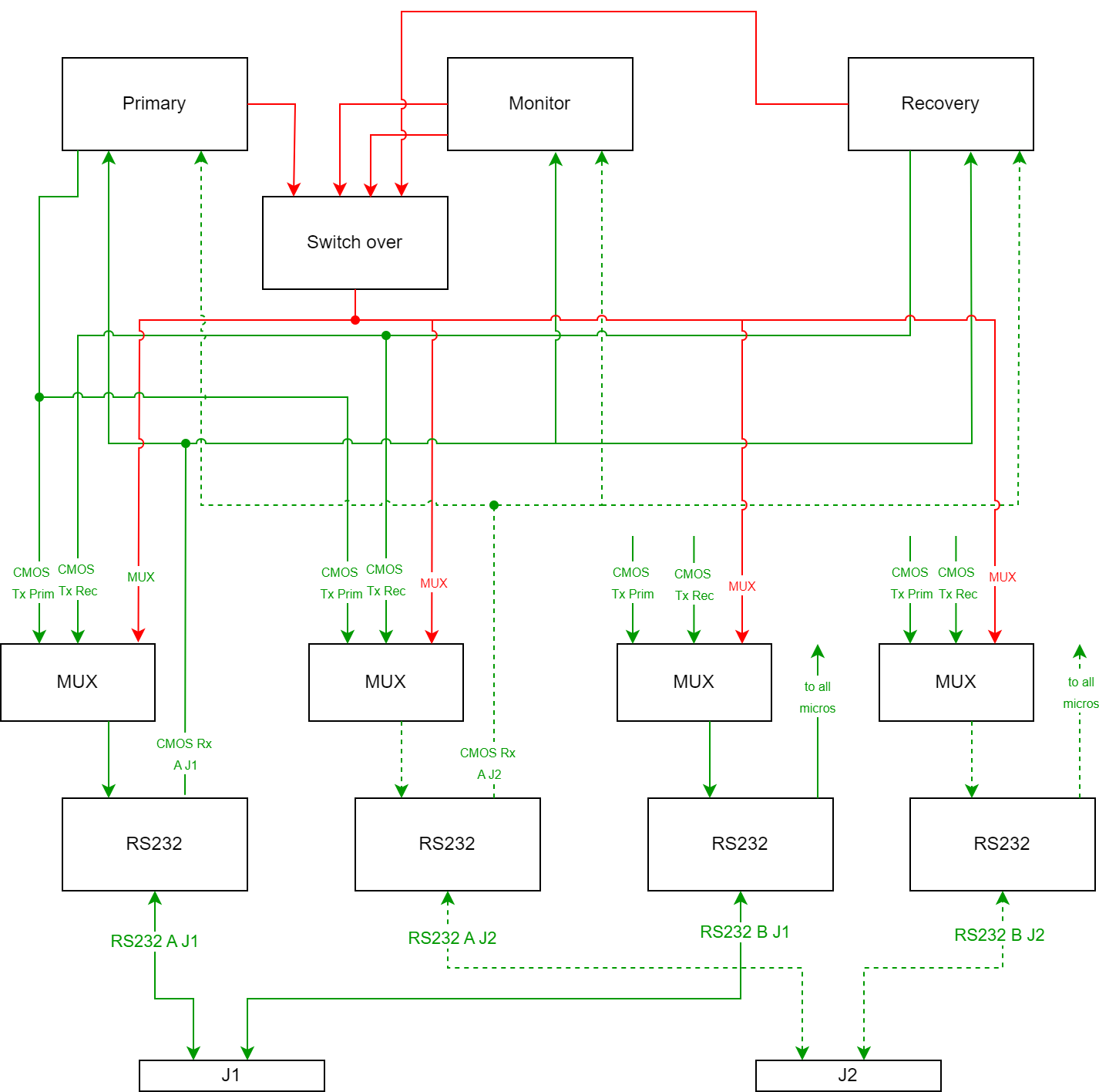
The system includes 2x RS232 and 2x RS485 ports, both of them redundant and available through J1 (2x RS232 & 2x RS485) and J2 connector (2x RS232 & 2x RS485).
As shown in the diagram, transmission is multiplexed: Primary and Recovery provide their own transmit line (CMOS Tx) to a MUX, and the Switch over block selects which core actually transmits through the RS232 (or RS485) transceiver towards the connector. Reception is shared, so the incoming data reaches all three cores simultaneously. This muxed-Tx / shared-Rx scheme is replicated for the ports on J1 and J2.
Note
Unlike CAN, the RS232 ports on J1 and J2 are the same bus because the same Tx signal is routed to both connectors. For example, CAN A on J1 and CAN A on J2 are independent buses.
PWM / Digital outputs
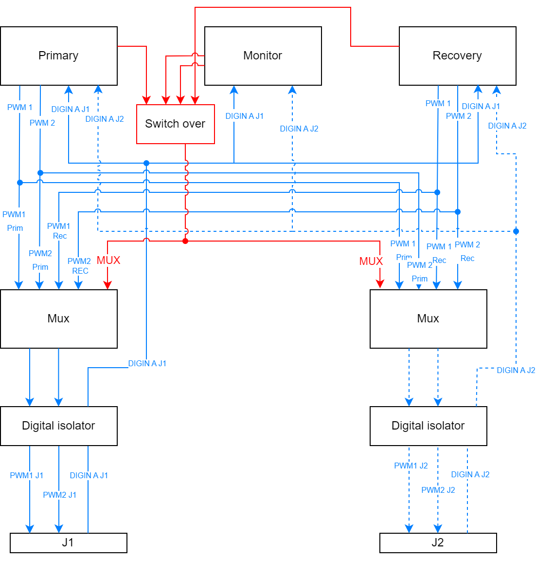
4 redundant digital outputs are included in REx. These 4 signals are available in both J1 (4x PWM) and J2 (4x PWM) connectors and can be configured as a PWM signal or a generic 5V digital output.
The diagram shows how each output is generated: Primary and Recovery provide their PWM lines to a Mux that, commanded by the Switch over block, forwards only the signals from the core currently in command. The selected outputs then pass through a digital isolator before reaching the connector, protecting the autopilot from electrical faults on the actuator side. The same path exists on J1 and J2, and the shared 5V digital inputs (DIGIN) are routed back to the cores.
Analog inputs
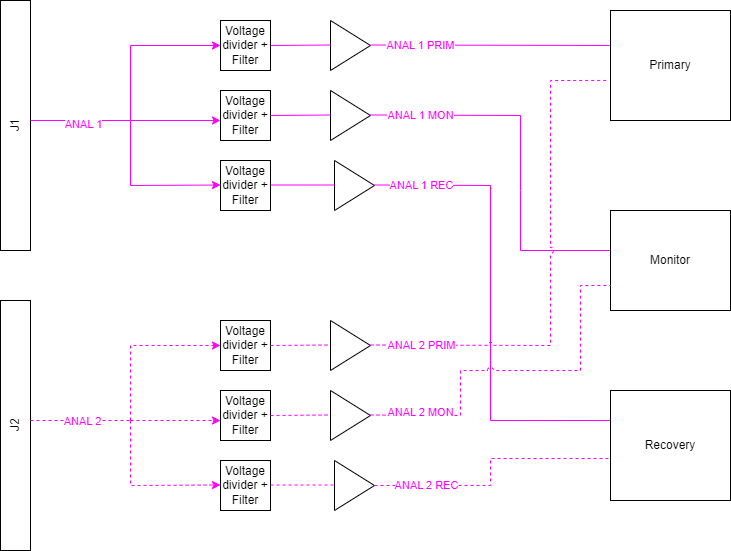
The Veronte Autopilot REx includes 6 Analog signal inputs (3x J1 & 3x J2) that can be used as independent signals or as 3 redundant channels. Voltage inputs are available as follows: 2x5V, 2x12V, 2x54V.
Each analog input is shared among the three cores with independent signal conditioning: as shown in the diagram, the input coming from the connector (e.g. ANAL 1 on J1) is split into three identical stages — a voltage divider + filter followed by a buffer amplifier — one per core (PRIM, MON and REC). This lets all three cores read the same external signal simultaneously while keeping their measurement chains isolated from each other.
Digital inputs
4x 5V Digital inputs are also available (2x J1 & 2x J2), being possible to use them as 4 independent channels or as 2x redundant inputs.
Ethernet
The Veronte Autopilot REx includes 2x Ethernet ports for datalink communications and configuration. One port is available on each connector (J1 & J2) and both are shared through an internal switch.
ARINC 429
The Veronte Autopilot REx includes 4x ARINC 429 Tx ports, 2x J1 and 2x J2, that can be configured as 4 independent ports or as 2x redundant signals. For ARINC 429 reception, there are 8 inputs available, being 4 of them available in J1 and 4 available on J2.
Redundancy and safety
- Primary-Monitor-Recovery architecture: The three cores run in parallel, each with its own sensor suite and its own GNC processing. The Monitor continuously checks the health and consistency of the other cores. If the Primary fails or asserts its self-exclusion signal, the Monitor switches control to the Recovery core through hardware multiplexers, keeping the transition transparent to the actuators.
- No single point of failure: Physical and functional isolation between cores (independent power rails, dedicated sensor suites and isolated buses) prevents a fault in one lane — or a self-exclusion signal — from affecting the others, keeping the system fail-operational.
- Dual-channel I/O redundancy: Every bus available on connector J1 is duplicated on connector J2 as an isolated secondary lane. A wiring fault or the loss of one connector does not interrupt data flow between the cores and external peripherals.
- Redundant power supply: The REx exposes two independent power inputs on connector J1 and two on connector J2. This cross-linked scheme allows the autopilot to be fed from separate batteries or regulators through different connectors, so the loss of a harness or a single power rail does not interrupt operation.
Veronte Autopilot REx also includes a separate flight termination voting logic, completely dissimilar and implemented in simple hardware, whose purpose is to give the internal cores a way to decide whether a flight termination signal should be activated or not. This arbitration between cores is handled by a voting circuit called Switch Over (SO), described in detail in the Switch Over — Fault Handling section of this manual.
Operation modes
The Veronte Autopilot REx offers an adaptable operational framework designed to meet rigid aerospace certification standards, combining different software environments and hardware topologies while keeping a certified fail-operational safety net.
Redundancy deployment architectures
By using the same core technology in different configurations, integrators can choose between two deployment topologies:
- Embedded redundancy: A single Veronte Autopilot REx unit provides the complete triple-redundant, fail-operational system on its own, with all redundancy managed internally as described in the Redundancy and safety section. This is the most optimized solution for low-SWaP platforms (e.g. tactical UAVs), simplifying the wiring harness while meeting DAL-B standards.
- Distributed redundancy (DRx): Two or more REx units are installed in geographically different zones of the airframe (e.g. nose and tail), interconnected via redundant high-speed buses to share health status and sensor data. This protects against zonal failures (localized damage, fire or interference): if one unit is lost, another located in a safe zone takes over flight authority instantaneously.
Variants
| Variant name | Reference |
|---|---|
| With remote ID | P006146 |
| With ADS-B | P006147 |
Sensor Specifications
The Veronte Autopilot REx sensor suite provides dedicated sensor sets and isolation for each internal core. Each of the three cores is equipped with its own sensors — IMUs (accelerometers and gyroscopes), magnetometers, barometers (static pressure), differential pressure sensors (dynamic pressure) and GNSS — supporting independent GNC processing and reducing the impact of faults in an individual sensor chain. External sensors can also be integrated.
Note
All three cores use the same types of sensors, except for GNSS: the Primary and Recovery cores use GNSS 1, while the Monitor core uses GNSS 2.
| Accelerometers (3-axis each one) | ||
|---|---|---|
| Specification | IMU 1 | IMU 2 |
| Range | Up to 24 g (configurable) | 8 g |
| Maximum shock | 10,000 g | 2,000 g |
| Sensitivity | 10,920 LSB/g for gFS3g 1,365 LSB/g for gFS24g |
262,144,000 LSB/g |
| Update Time | 1 ms | |
| Error | 190 Z axis, 160 X & Y axis (noise density) |
23 (noise density) |
| Offset | ± 20 mg | ± 0.6 mg |
| Gyroscopes (3-axis each one) | ||
|---|---|---|
| Specification | IMU 1 | IMU 2 |
| Range | 125 to 2,000 °/sec | 500 °/sec |
| Sensitivity | 262 to 16 LSB/°/sec | 2,621,440 to 40 LSB/°/sec |
| Update Time | 1 ms | |
| RMS noise | 0.1 °/sec | 0.08 °/sec |
| Offset | ±1 °/sec | ±0.1 °/sec |
| Magnetometers | ||
|---|---|---|
| Specification | Magnetometer 1 | Magnetometer 2 |
| Range | ±2000 T | ±800 T |
| Sensitivity | ±100 T | 50 to 13 nT |
| RMS Noise | 190 nT (X & Y axis) 450 nT (Z axis) |
30 to 15 nT |
| Offset | ±2 T | - |
| Static Pressure | ||
|---|---|---|
| Specification | Sensor 1 | Sensor 2 |
| Range | 1,000 - 120,000 Pa | 30,000 - 120,000 Pa |
| Band Error | 250 Pa | 100 Pa |
| Resolution | 1.2 to 6.5 Pa | 6 Pa |
| Update Time | 0.5 to 8.22 ms | 27.6 ms |
| Dynamic Pressure Sensor | |
|---|---|
| Specification | Pitot |
| Range | 25,000 to 125,000 Pa |
| Band Error | ±250 Pa |
| Resolution | ±22 Pa |
| Update Time | 5 ms |
| Bias | ±7 Pa |
| GNSS Receivers | ||||
|---|---|---|---|---|
| Specification | GNSS 1 | GNSS 2 | ||
| Constellations | BeiDou, Galileo, GLONASS, GPS, NavIC, QZSS | BeiDou, Galileo, GLONASS, GPS, NavIC, QZSS, SBASS | ||
| Bands | L1 C/A, L2C, L1OF, L2OF, E1 B/C, E5a, B1I, B3I | L1 C/A, L2C, B1I, B1C, E1, L1 C/B, L5 | ||
| RTK Support | Yes (via PPP-RTK with SPARTN/CLAS) | Yes | ||
| RTK Position Accuracy | Horizontal | 0.006 m + 1 ppm | 0.006 m + 0.5 ppm | |
| Vertical | 0.01 m + 1 ppm | 0.01 m + 1 ppm | ||
| SBAS Position Accuracy | Horizontal | 0.6 m | 0.6 m | |
| Vertical | 1.0 m | 0.8 m | ||
| Velocity Accuracy | 0.03 m/s | 0.03 m/s | ||
| Update Rate | RTK: Up to 5 Hz | 100 Hz | ||
| Anti-jamming | RF interference and jamming detection and reporting | AIM+ Premium Industry leading anti-jamming | ||
| Anti-spoofing | Spoofing detection and reporting | Anti-spoofing interference monitoring | ||
| Advanced Functions |
|
|
||
Mechanical and Electrical specifications
| Variable | Value |
|---|---|
| Weight | 825 g With Damping System: + 150 g |
| Operating temperature | -40 ºC to 65 ºC |
| Storage temperature | -55 ºC to 85 ºC |
| Protection Rating | IP67 |
| Power input voltage | 8 to 54 V |
| Power consumption | Up to 17.47 W |
| Maximum acceleration | 32 g |
| Connectors | MIL-DTL-38999 Series |
| Protections | Reverse polarity, short circuit, EMI/EMC |
| Redundancy | Triple redundancy with dissimilarity |
| I/O | Dual-channel redundant |
| Diagnostics | Switch-over, multiplexers, and BIT |
| FTS (Flight Termination System) | Independent fail-safe in case of total failure |
| Software | Veronte OS DO178C DAL B or custom code |
| Hardware | DO254 DAL B |
Dimensions
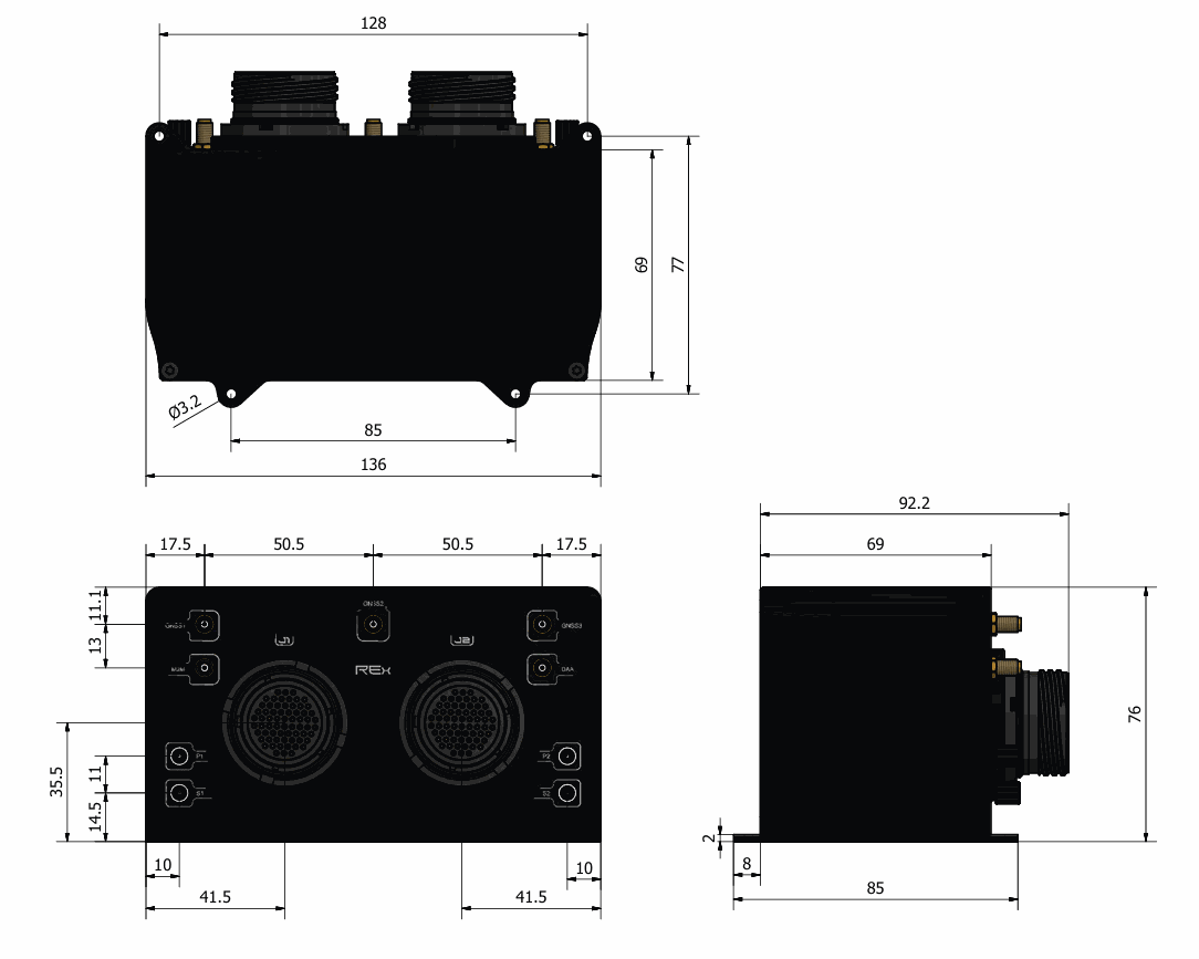
M3 screws are recommended for mounting. In saline environments such as coastal and oceanic, the screw material should be stainless steel.
Interfaces
Connector layout
The Veronte Autopilot REx exposes two main high-density connectors (J1 and J2) for all flight-critical I/O, plus dedicated SSMA antenna ports for GNSS, M2M and DAA, and pressure ports for pitot and static sensing. J1 and J2 are wired as a dual-channel configuration, so the complete loss of one connector or harness does not prevent the autopilot from commanding actuators or receiving telemetry. For the electrical pinout of J1 and J2 see the Pinout - Hardware Installation section of this manual.

| Connector | Description |
|---|---|
| J1 | MIL-DTL-38999 high-density connector for flight-critical I/O (primary channel of the dual-channel scheme) |
| J2 | MIL-DTL-38999 high-density connector for flight-critical I/O (secondary channel of the dual-channel scheme) |
| GNSS1 | SSMA connector for the GNSS antenna dedicated to the Primary core |
| GNSS2 | SSMA connector for the GNSS antenna dedicated to the Monitor core |
| GNSS3 | SSMA connector for the GNSS antenna dedicated to the Recovery core |
| M2M |
SSMA connector for the internal 4G LTE module, used for BVLOS operations
Warning
If the BLOS module is enabled, a suitable antenna must be connected to this port. The 4G Antenna with the Embention reference P000112 is recommended. |
| DAA |
SSMA connector for the embedded Remote ID or ADS-B (In & Out) module
Warning
When using ADS-B or Remote ID, there must be an adequate antenna or load connection to the DAA port. |
| PITOT (x2) | Two independent dynamic pressure ports (Int. D. 2.5 mm x Out. D. 4 mm) for redundant airspeed sensing |
| STATIC (x2) | Two independent static pressure ports (Int. D. 2.5 mm x Out. D. 4 mm) for redundant altitude sensing |
Mating connectors
| Abbreviation | Autopilot REx connector | Mating connector |
|---|---|---|
| GNSS | GNSS antenna (SSMA Jack Female) | SSMA male Plug, low-loss cable is recommended. Active Antenna GNSS:
|
| DAA | SSMA Jack female for ADS-B or Remote ID antenna | SSMA male Plug, low-loss cable is recommended |
| M2M | SSMA Jack female for M2M (4G LTE) antenna | |
| J1 | MIL-DTL-38999 Series high-density connector (66P) |
|
| J2 | MIL-DTL-38999 Series high-density connector (66P) |
|
Environmental test - DO160
The Veronte Autopilot REx is engineered to meet the DO-160G standards required for aeronautical certification, ensuring reliability in the most hostile flight conditions.
Beyond environmental durability, the REx is hardened against electromagnetic threats, featuring high-level EMI/EMC shielding and HIRF protection to prevent interference from high-power transmitters.
© 2026 Embention. All rights reserved.