Hardware Installation
Mechanical
Veronte Autopilot REx is covered with an aluminium enclosure with enhanced EMI shielding and IP protection, with 825 g as total weight.
Pressure lines
Veronte Autopilot REx has four pressure input lines; two for static pressure to determine the absolute pressure and two for pitot in order to determine the dynamic pressure.
For the fittings it is recommended to use a polyurethane tube of 2.5 mm inner diameter and 4 mm outer diameter.
-
Pressure Intake
- Pressure intakes must be located in order to prevent clogging.
- Do not install pressure intakes on the propeller flow.
- Design pressure tubing path in order to avoid tube constriction.
-
Static Pressure
- It is not recommended to use inside fuselage pressure if it is not properly vented.
-
Pitot Tube
- Pitot tube must be installed facing the airflow.
- It is recommended to install it near the aircraft's x axis in order to avoid false measures during manoeuvres.
- For low-speed aircraft it is recommended at least 6.3 mm tubes to prevent any rain obstruction.
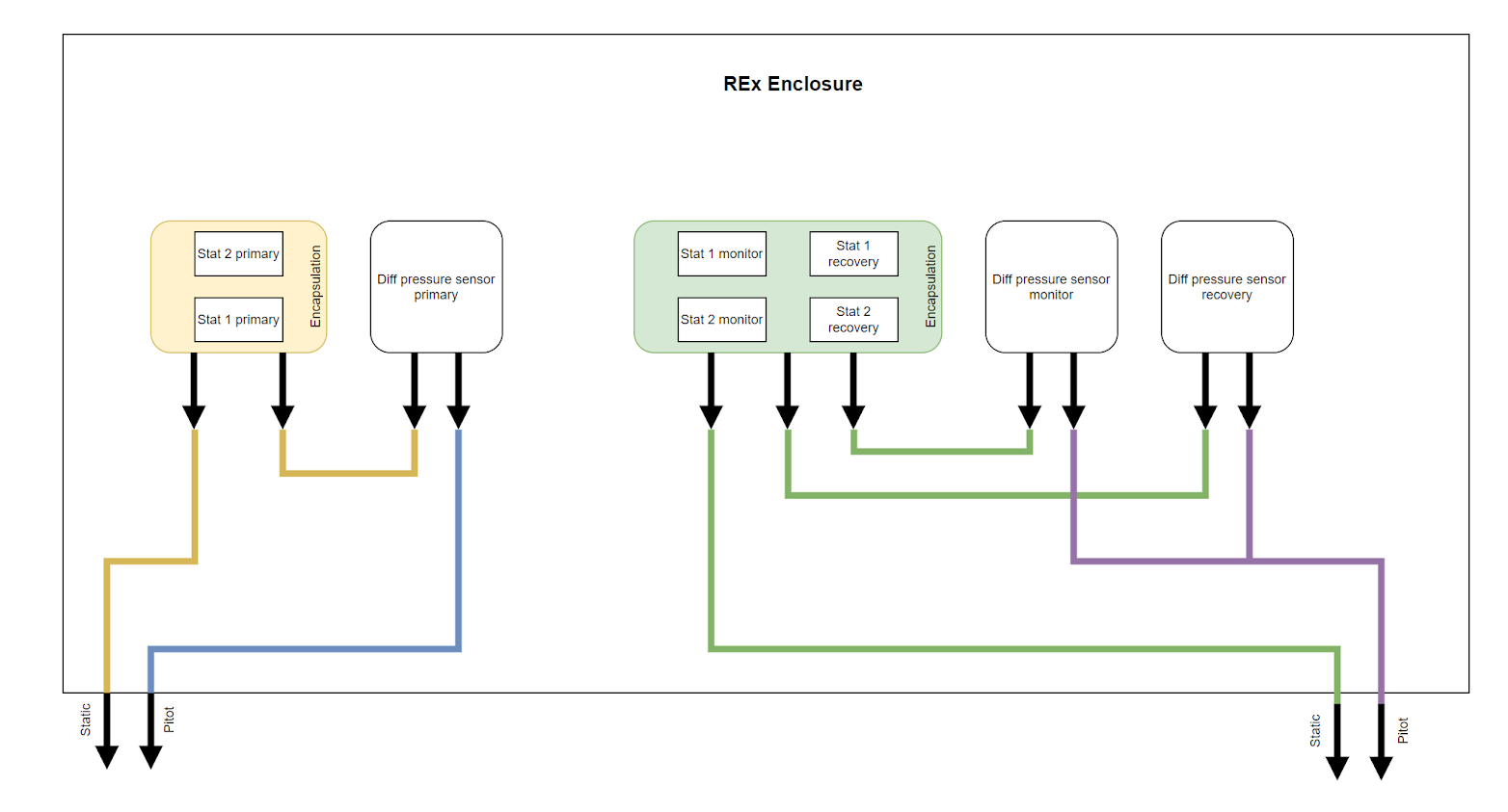
The diagram above shows how the four external ports (2 static + 2 pitot) are distributed among the internal sensors of the three cores. The lines are grouped into two independent pneumatic channels, each with one static and one pitot port: one channel feeds the Primary core, while the other is shared by the Monitor and Recovery cores. Within each core, static pressure is measured by two redundant encapsulated barometers (Stat 1 and Stat 2), and dynamic pressure is obtained from a dedicated differential pressure sensor referenced between the pitot and static lines.
Location
The location of Veronte Autopilot REx has no restrictions. It is only required to configure its relative position respect to the centre of mass of the aircraft and the GNSS antenna.
Orientation
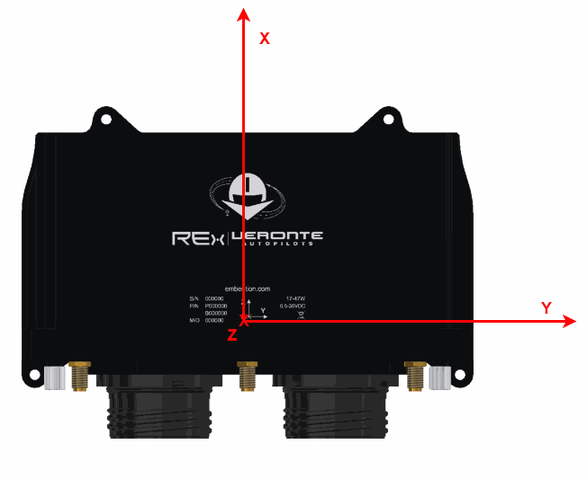
The orientation of Veronte Autopilot REx has no restrictions either. It is only required to configure axes respect to the aircraft by means of a rotation matrix or a set of correspondences between axes. The configuration of the orientation can be easily configured using 1x PDI Builder.
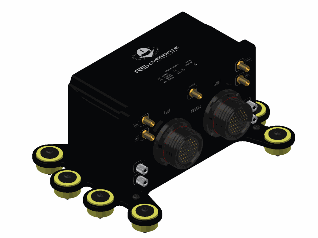
Axes are printed on the Autopilot REx box, as shown below.
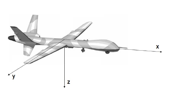
Aircraft coordinates are defined by the standard aeronautical conventions, shown in the following figure.
Vibration Isolation
Although Veronte Autopilot REx rejects noise and high-frequency vibration modes with electronic filters, there may be situations where external isolation is needed.
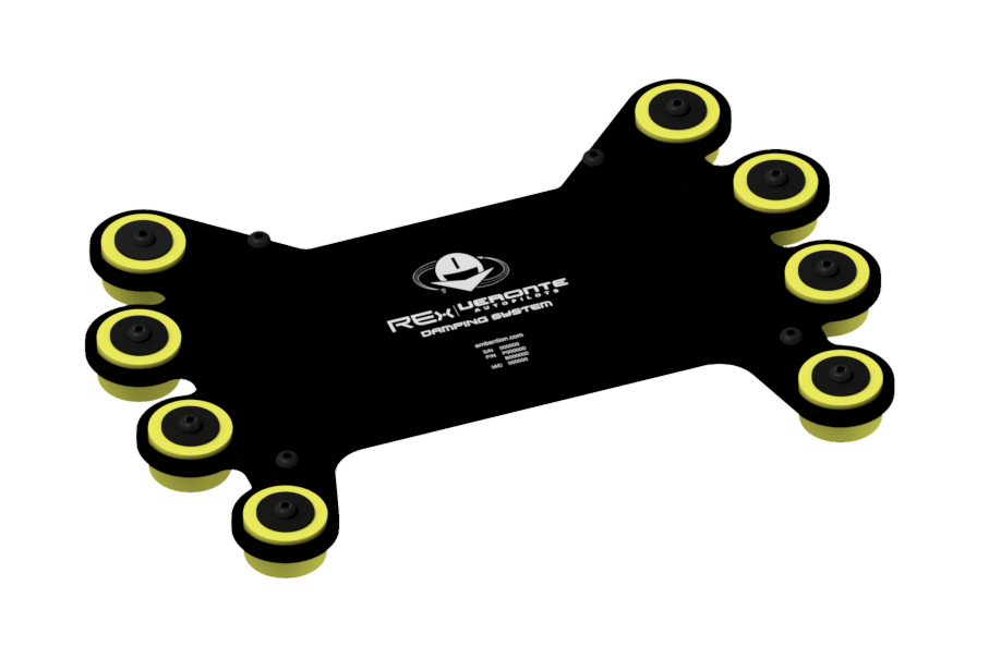
Autopilot REx can be mounted in different ways in order to reject the airframe vibration, but it is recommended to use the Damping System designed for that purpose. It covers a wide frequency range of different aircraft types.
Note
The user should take into account that wiring should be loose enough so that vibrations are not transmitted to Autopilot REx.
Damping System
Embention offers the Damping System as a solution to isolate Veronte Autopilot REx from vibrations.
Important
Only effective with Autopilot REx in horizontal position.
This damping system weighs approximately 150 g.
Dimensions
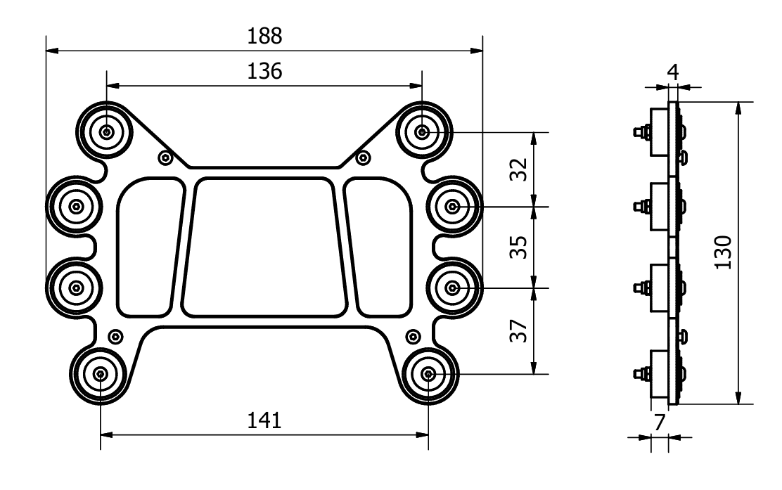
Assembly steps
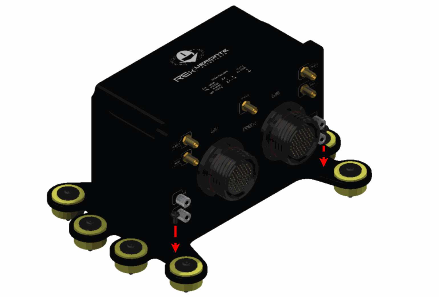
To assemble the Damping System into a vehicle with an Autopilot REx, read the following steps.
-
Remove the eight nuts located under the platform.
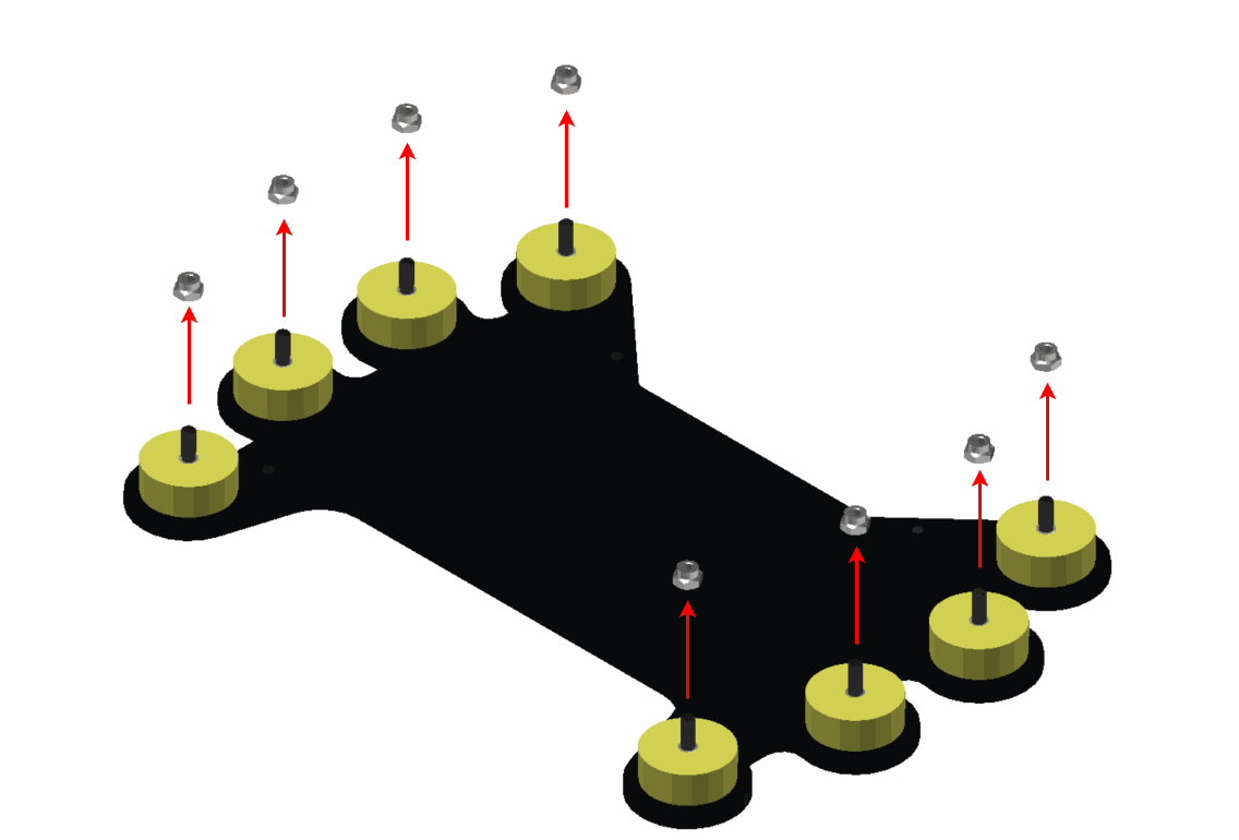
Step 1 -
Screw the platform on the aircraft frame. The included screws have M3.
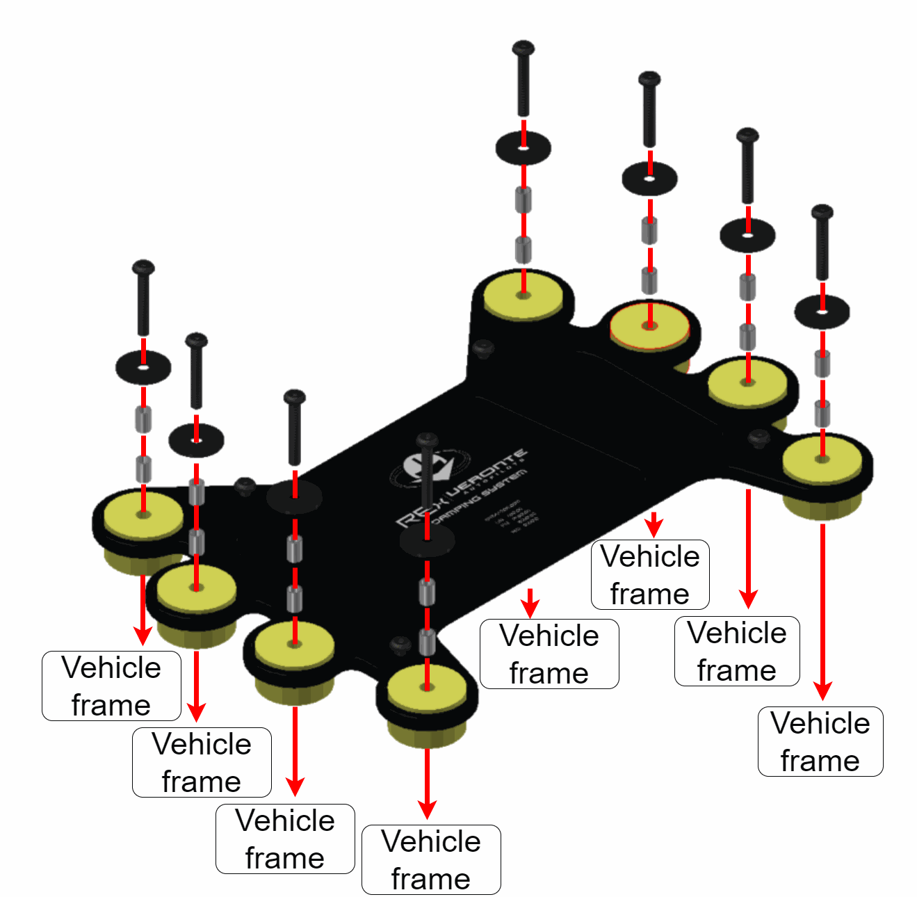
Step 2 -
Screw the Autopilot REx on the Damping system.
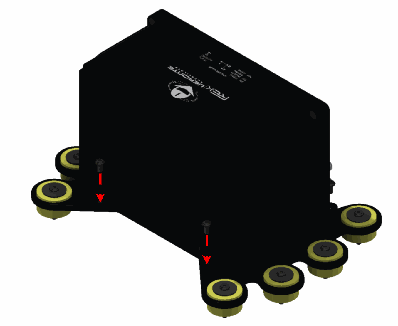
Step 3
Antenna Integration
The system uses different kinds of antenna to operate, they must be installed on the airframe. Here you can find some advice for obtaining the best performance and for avoiding antenna interferences.
-
Antenna Installation
- Maximize separation between antennas as much as possible.
- Keep antennas far away from alternators or other interference generators.
- Always isolate the antenna ground panel from the aircraft structure.
- Make sure antennas are securely mounted.
- Always use high-quality RF wires minimising the wire length.
- Always follow the antenna manufacturer manual.
- SSMA connections shall be tightened applying 1Nm of torque.
- For all-weather aircraft, insert SSMA lightning protectors.
-
GNSS Antenna
- Antenna top side must point to the sky.
- Install them on a top surface with direct sky view.
- Never place wires or parts made of metal or carbon above the antenna.
- It is recommended to install antennas on a small ground plane.
- For all-weather aircrafts, insert SSMA lightning protectors.
-
Recommended specifications for GNSS antennas
Specifications Range Antenna frequency L1 1561.098 MHz to 1602 MHz Antenna frequency L2 1207.14 MHz to 1246 MHz Amplifier gain 17 dB to 35 dB Out-of-band rejection 40 dB
Note
Higher values are preferable.
30 dB is considered the minimum acceptable value.Polarization RHCP (Right-Hand Circular Polarization) Minimum supply voltage 2.7 V to 3.3 V Maximum supply current 50 mA
Electrical
Power supply
Autopilot REx can use unregulated DC (8 V to 54 V). All power supply pins are not common. It is possible to supply them with different voltages since they are internally protected with diodes. Nonetheless, all power supply pins must be connected to a power supply, in order to guarantee that Autopilot REx will work in case of failing one of them. These pins are summarized in the following table:
| Connector | PIN | Signal |
|---|---|---|
| Connector J1 | 3 | VIN PRIM |
| 5 | VIN MON | |
| 8 | VIN PRIM | |
| Connector J2 | 3 | VIN REC |
| 5 | VIN MON | |
| 8 | VIN REC |
LiPo batteries between 2S and 8S can be used without voltage regulation. Remaining battery can be controlled by the internal voltage sensor and by configuring the voltage warnings on the PC application.
For higher voltage installations, voltage regulators must be used. For dimensioning voltage regulators take into account that a blocked servo can activate regulator thermal protection.
Warning
Power Veronte Autopilot REx out of the given range can cause irreversible damage to the system. Please read carefully the manual before powering the system.
Autopilots and servos can be powered by the same or different batteries. In case there are more than one battery on the system, a single point ground union is needed to ensure a good performance. The ground signal should be isolated from other system ground references (e.g. engines).
It is recommendable to use independent switches for autopilot and motor/actuators. During the system initialization, PWM signal will be fixed to low level (0V), please make sure that actuators/motor connected support this behavior before installing a single switch for the whole system.
Power Domains
Veronte Autopilot REx implements a cross-linked, quad-input power scheme with two independent power inputs on Connector J1 and two on Connector J2. This allows the autopilot to be fed from separate battery or regulator sources across different connectors, so that the loss of an entire cable harness or of a single power rail never interrupts operation.
The four inputs are internally organized in two redundant power domains (A and B), electrically isolated from each other:
- Connector J1 and all its associated peripherals are powered by Power Domain A.
- Connector J2 and all its associated peripherals are powered by Power Domain B.
This separation enables redundancy management against internal power failures. For example, if the aircraft requires measuring a critical temperature from an external device, the user can connect two analog sensors to inputs on different power domains (one on J1 and one on J2) so that the measurement remains available even if one domain fails.
Pinout
Warning
Pins can transfer 2 A as maximum current.
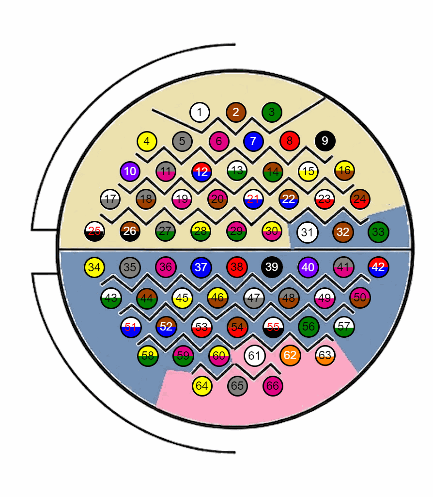
Warning
Check the pin number before connecting. The color code is repeated 2 times due to the amount of pins, except for pins 56 and 57. First section (yellow) corresponds to pins 1-30, the second section (blue) to pins 31-60. A third one (pink) with a different color pattern corresponds to pins 61-66.
Connector J1 pinout
| PIN | Signal | Type | Internal Power Domain | Description |
|---|---|---|---|---|
| 1 | GND MON | GROUND | A | Supply negative for monitor, connected together with J2 pin 1 |
| 2 | GND PRIM | GROUND | A | Supply negative for primary |
| 3 | VIN PRIM | POWER | A | Supply positive for Primary |
| 4 | J1_ATX0_P | OUTPUT | A | J1 ARINC 429 channel 0 positive output |
| 5 | VIN MON | POWER | A | Supply positive for Monitor, connected together with J2 pin 5 |
| 6 | J1_ARX0_P | INPUT | A | J1 ARINC 429 channel 0 positive input |
| 7 | GND PRIM | GROUND | A | Supply negative for primary |
| 8 | VIN PRIM | POWER | A | Supply positive for Primary |
| 9 | J1_CAN_MUX_A_P | CAN BUS | A | CAN A J1 positive (muxed functionality) |
| 10 | J1_ATX0_N | OUTPUT | A | J1 ARINC 429 channel 0 negative output |
| 11 | J1_ATX1_P | OUTPUT | A | J1 ARINC 429 channel 1 positive output |
| 12 | J1_ARX1_P | INPUT | A | J1 ARINC 429 channel 1 positive input |
| 13 | J1_ARX0_N | INPUT | A | J1 ARINC 429 channel 0 negative input |
| 14 | ANALOG IN 1 | INPUT | A | Analog input 1 (0V..5V) |
| 15 | ANALOG IN 3 | INPUT | A | Analog input 3 (0V..12V) |
| 16 | J1_CAN_MUX_A_N | CAN BUS | A | CAN A J1 negative (muxed functionality) |
| 17 | J1_DIGIN_A | INPUT | A | 5V digital input |
| 18 | J1_ARINC_GND | GROUND | A | Negative for ARINC 429 inputs of J1 connector |
| 19 | J1_ATX1_N | OUTPUT | A | J1 ARINC 429 channel 1 negative output |
| 20 | J1_ARX1_N | INPUT | A | J1 ARINC 429 channel 1 negative input |
| 21 | J1 ANALOG GND | GROUND | A | Negative for all J1 connector analog signals |
| 22 | ANALOG IN 5 | INPUT | A | Analog input 5 (0V..54V) |
| 23 | J1_CAN_GND | CAN GROUND | A | Negative for all J1 connector CAN signals |
| 24 | J1_CAN_MUX_B_P | CAN BUS | A | CAN B J1 positive (muxed functionality) |
| 25 | J1_DIGIN_B | INPUT | A | 5V digital input |
| 26 | J1 GND IO | GROUND | A | Negative for PWMs and Digital inputs of J1 connector |
| 27 | - | - | - | - |
| 28 | J1_ARINC_GND | GROUND | A | Negative for ARINC 429 inputs of J1 connector |
| 29 | J1 GND IO | GROUND | A | Negative for Opendrain FTS output of J1 |
| 30 | J1_PWM4 | OUTPUT | A | Digital output 4 of J1 |
| 31 | J1_PWM1 | OUTPUT | A | Digital output 1 of J1 |
| 32 | J1_CAN_SHD_C_P | CAN BUS | A | CAN C J1 positive (shared functionality) |
| 33 | J1_CAN_MUX_B_N | CAN BUS | A | CAN B J1 negative (muxed functionality) |
| 34 | J1_FTS | OUTPUT OPEN-DRAIN | A | Flight termination system of J1 |
| 35 | J1_INB_485_N | INPUT | A | J1 RS485 B negative input |
| 36 | J1_ARX2_P | INPUT | A | J1 ARINC 429 channel 2 positive input |
| 37 | J1_ARX2_N | INPUT | A | J1 ARINC 429 channel 2 negative input |
| 38 | - | - | - | - |
| 39 | J1_GND_RS232 | GROUND | A | Negative for RS232 of J1 connector |
| 40 | J1_PWM2 | OUTPUT | A | Digital output 2 of J1 |
| 41 | J1_CAN_SHD_C_N | CAN BUS | A | CAN C J1 negative (shared functionality) |
| 42 | J1_CAN_SHD_D_P | CAN BUS | A | CAN D J1 positive (shared functionality) |
| 43 | J1_INB_485_P | INPUT | A | J1 RS485 B positive input |
| 44 | J1_OUTB_485_N | OUTPUT | A | J1 RS485 B negative output |
| 45 | J1_GND_RS485 | GROUND | A | Negative for RS485 of J1 connector |
| 46 | J1_ARX3_P | INPUT | A | J1 ARINC 429 channel 3 positive input |
| 47 | J1_GND_RS485 | GROUND | A | Negative for RS485 of J1 connector |
| 48 | J1_CAN_GND | GROUND | A | Negative for all J1 connector CAN signals |
| 49 | J1_PWM3 | OUTPUT | A | Digital output 3 of J1 |
| 50 | J1_CAN_SHD_D_N | CAN BUS | A | CAN D J1 negative (shared functionality) |
| 51 | J1_OUTB_485_P | OUTPUT | A | J1 RS485 B positive output |
| 52 | J1_INA_485_P | INPUT | A | J1 RS485 A positive input |
| 53 | J1_ARX3_N | INPUT | A | J1 ARINC 429 channel 3 negative input |
| 54 | J1_GND_RS232 | GROUND | A | Negative for RS232 of J1 connector |
| 55 | J1_ETH_CHASSIS | ETH CHASSIS | A | Ethernet chassis, connected to enclosure |
| 56 | J1_RX_N | INPUT | A | Ethernet Rx negative of J1 connector |
| 57 | J1_RX_P | INPUT | A | Ethernet Rx positive of J1 connector |
| 58 | J1_INA_485_N | INPUT | A | J1 RS485 A negative input |
| 59 | J1_OUTA_485_N | OUTPUT | A | J1 RS485 A negative output |
| 60 | J1_RS232_TX_A | OUTPUT | A | RS232 A Tx of J1 |
| 61 | J1_RS232_TX_B | OUTPUT | A | RS232 B Tx of J1 |
| 62 | J1_TX_N | OUTPUT | A | Ethernet Tx negative of J1 connector |
| 63 | J1_TX_P | OUTPUT | A | Ethernet Tx positive of J1 connector |
| 64 | J1_OUTA_485_P | OUTPUT | A | J1 RS485 A positive output |
| 65 | J1_RS232_RX_A | INPUT | A | RS232 A Rx of J1 |
| 66 | J1_RS232_RX_B | INPUT | A | RS232 B Rx of J1 |
Connector J2 pinout
| PIN | Signal | Type | Internal Power Domain | Description |
|---|---|---|---|---|
| 1 | GND MON | GROUND | B | Supply negative for monitor, connected together with J1 pin 1 |
| 2 | GND REC | GROUND | B | Supply negative for recovery |
| 3 | VIN REC | POWER | B | Supply positive for Recovery |
| 4 | J2_ATX0_P | OUTPUT | B | J2 ARINC 429 channel 0 positive output |
| 5 | VIN MON | POWER | B | Supply positive for Monitor, connected together with J1 pin 5 |
| 6 | J2_ARX0_P | INPUT | B | J2 ARINC 429 channel 0 positive input |
| 7 | GND REC | GROUND | B | Supply negative for recovery |
| 8 | VIN REC | POWER | B | Supply positive for recovery |
| 9 | J2_CAN_MUX_A_P | CAN BUS | B | CAN A J2 positive (muxed functionality) |
| 10 | J2_ATX0_N | OUTPUT | B | J2 ARINC 429 channel 0 negative output |
| 11 | J2_ATX1_P | OUTPUT | B | J2 ARINC 429 channel 1 positive output |
| 12 | J2_ARX1_P | INPUT | B | J2 ARINC 429 channel 1 positive input |
| 13 | J2_ARX0_N | INPUT | B | J2 ARINC 429 channel 0 negative input |
| 14 | ANALOG IN 2 | INPUT | B | Analog input 2 (0V..5V) |
| 15 | ANALOG IN 4 | INPUT | B | Analog input 4 (0V..12V) |
| 16 | J2_CAN_MUX_A_N | CAN BUS | B | CAN A J2 negative (muxed functionality) |
| 17 | J2_DIGIN_A | INPUT | B | 5V digital input |
| 18 | J2_ARINC_GND | GROUND | B | Negative for ARINC 429 inputs of J2 connector |
| 19 | J2_ATX1_N | OUTPUT | B | J2 ARINC 429 channel 1 negative output |
| 20 | J2_ARX1_N | INPUT | B | J2 ARINC 429 channel 1 negative input |
| 21 | J2 ANALOG GND | GROUND | B | Negative for all J2 connector analog signals |
| 22 | ANALOG IN 6 | INPUT | B | Analog input 6 (0V..54V) |
| 23 | J2_CAN_GND | GROUND | B | Negative for all J2 connector CAN signals |
| 24 | J2_CAN_MUX_B_P | CAN BUS | B | CAN B J2 positive (muxed functionality) |
| 25 | J2_DIGIN_B | INPUT | B | 5V digital input |
| 26 | J2 GND IO | GROUND | B | Negative for PWMs and Digital inputs of J2 connector |
| 27 | - | - | - | - |
| 28 | J2_ARINC_GND | GROUND | B | Negative for ARINC 429 inputs of J2 connector |
| 29 | J2 GND IO | GROUND | B | Negative for Opendrain FTS output of J2 |
| 30 | J2_PWM4 | OUTPUT | B | Digital output 4 of J2 |
| 31 | J2_PWM1 | OUTPUT | B | Digital output 1 of J2 |
| 32 | J2_CAN_SHD_C_P | CAN BUS | B | CAN C J2 positive (shared functionality) |
| 33 | J2_CAN_MUX_B_N | CAN BUS | B | CAN B J2 negative (muxed functionality) |
| 34 | J2_FTS | OUTPUT OPEN-DRAIN | B | Flight termination system of J2 |
| 35 | J2_INB_485_N | INPUT | B | J2 RS485 B negative input |
| 36 | J2_ARX2_P | INPUT | B | J2 ARINC 429 channel 2 positive input |
| 37 | J2_ARX2_N | INPUT | B | J2 ARINC 429 channel 2 negative input |
| 38 | - | - | - | - |
| 39 | J2_GND_RS232 | GROUND | B | Negative for RS232 of J2 connector |
| 40 | J2_PWM2 | OUTPUT | B | Digital output 2 of J2 |
| 41 | J2_CAN_SHD_C_N | CAN BUS | B | CAN C J2 negative (shared functionality) |
| 42 | J2_CAN_SHD_D_P | CAN BUS | B | CAN D J2 positive (shared functionality) |
| 43 | J2_INB_485_P | INPUT | B | J2 RS485 B positive input |
| 44 | J2_OUTB_485_N | OUTPUT | B | J2 RS485 B negative output |
| 45 | J2_GND_RS485 | GROUND | B | Negative for RS485 of J2 connector |
| 46 | J2_ARX3_P | INPUT | B | J2 ARINC 429 channel 3 positive input |
| 47 | J2_GND_RS485 | GROUND | B | Negative for RS485 of J2 connector |
| 48 | J2_CAN_GND | GROUND | B | Negative for all J2 connector CAN signals |
| 49 | J2_PWM3 | OUTPUT | B | Digital output 3 of J2 |
| 50 | J2_CAN_SHD_D_N | CAN BUS | B | CAN D J2 negative (shared functionality) |
| 51 | J2_OUTB_485_P | OUTPUT | B | J2 RS485 B positive output |
| 52 | J2_INA_485_P | INPUT | B | J2 RS485 A positive input |
| 53 | J2_ARX3_N | INPUT | B | J2 ARINC 429 channel 3 negative input |
| 54 | J2_GND_RS232 | GROUND | B | Negative for RS232 of J2 connector |
| 55 | J2_ETH_CHASSIS | ETH CHASSIS | B | Ethernet chassis, connected to enclosure |
| 56 | J2_RX_N | INPUT | B | Ethernet Rx negative of J2 connector |
| 57 | J2_RX_P | INPUT | B | Ethernet Rx positive of J2 connector |
| 58 | J2_INA_485_N | INPUT | B | J2 RS485 A negative input |
| 59 | J2_OUTA_485_N | OUTPUT | B | J2 RS485 A negative output |
| 60 | J2_RS232_TX_A | OUTPUT | B | RS232 A Tx of J2 |
| 61 | J2_RS232_TX_B | OUTPUT | B | RS232 B Tx of J2 |
| 62 | J2_TX_N | OUTPUT | B | Ethernet Tx negative of J2 connector |
| 63 | J2_TX_P | OUTPUT | B | Ethernet Tx positive of J2 connector |
| 64 | J2_OUTA_485_P | OUTPUT | B | J2 RS485 A positive output |
| 65 | J2_RS232_RX_A | INPUT | B | RS232 A Rx of J2 |
| 66 | J2_RS232_RX_B | INPUT | B | RS232 B Rx of J2 |
Harnesses
A wire harness is a structured assembly of cables and connectors used to organize and manage wiring in electrical and electronic systems. It is designed to ensure a tidy and secure installation of cables, preventing tangles, electromagnetic interference, and facilitating maintenance.
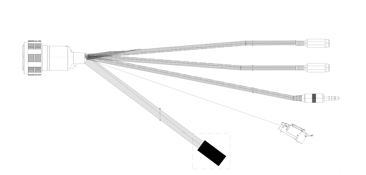
Veronte Autopilot REx 2.0 has the following compatible harness:
Dimensions
- Cables length: 50 cm
-
Harness plug dimensions:
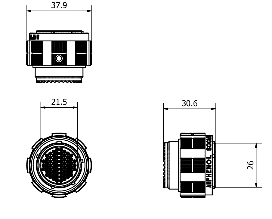
Harness connector (cm)
Pinout
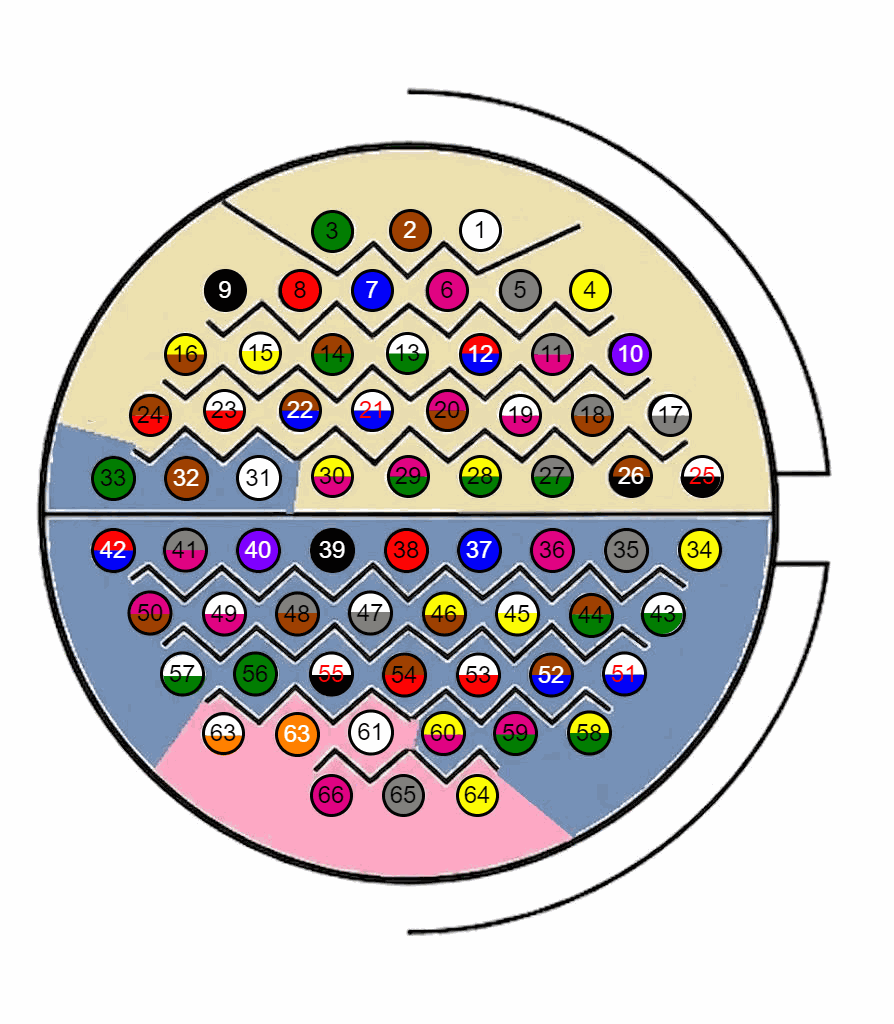
Veronte Harness
The pinout of the Veronte Harness is the same as the Connector J1 pinout above. The color code of the harness wires is given below.
Warning
Check the pin number before connecting. The color code is repeated 2 times due to the amount of pins, except for pins 56 and 57. First section (yellow) corresponds to pins 1-30, the second section (blue) to pins 31-60. A third one (pink) with a different color pattern corresponds to pins 61-66.
| PIN | Color Code | PIN | Color Code |
|---|---|---|---|
| 1 | White | 35 | Gray |
| 2 | Brown | 36 | Pink |
| 3 | Green | 37 | Blue |
| 4 | Yellow | 38 | Red |
| 5 | Gray | 39 | Black |
| 6 | Pink | 40 | Violet |
| 7 | Blue | 41 | Gray - Pink |
| 8 | Red | 42 | Red - Blue |
| 9 | Black | 43 | White - Green |
| 10 | Violet | 44 | Brown - Green |
| 11 | Gray - Pink | 45 | White - Yellow |
| 12 | Red - Blue | 46 | Yellow - Brown |
| 13 | White - Green | 47 | White - Gray |
| 14 | Brown - Green | 48 | Gray - Brown |
| 15 | White - Yellow | 49 | White - Pink |
| 16 | Yellow - Brown | 50 | Pink - Brown |
| 17 | White - Gray | 51 | White - Blue |
| 18 | Gray - Brown | 52 | Brown - Blue |
| 19 | White - Pink | 53 | White - Red |
| 20 | Pink - Brown | 54 | Brown - Red |
| 21 | White - Blue | 55 | White - Black |
| 22 | Brown - Blue | 56 | Green |
| 23 | White - Red | 57 | White - Green |
| 24 | Brown - Red | 58 | Yellow - Green |
| 25 | White - Black | 59 | Pink - Green |
| 26 | Brown - Black | 60 | Yellow - Pink |
| 27 | Gray - Green | 61 | White |
| 28 | Yellow - Green | 62 | Orange |
| 29 | Pink - Green | 63 | White - Orange |
| 30 | Yellow - Pink | 64 | Yellow |
| 31 | White | 65 | Gray |
| 32 | Brown | 66 | Pink |
| 33 | Green | ||
| 34 | Yellow |
Dev Harness REx 2.0
The pinout of this harness is the same as the Connector J1 pinout above. In addition, this harness has some connectors already implemented for easy operation. Below is detailed information on which pins these connectors are connected to:
| Connector | PIN | Signal |
|---|---|---|
| Power Input 1 | 1 | GND_MON |
| 5 | VIN_MON | |
| Power Input 2 | 2 and 7 | GND_PRIM |
| 3 and 8 | VIN_PRIM | |
| Jack connector | 17 | J1_DIGIN_A |
| 29 | J1_GND_IO | |
| Ethernet | 55 | J1_ETH_CHASSIS |
| 56 | J1_RX_N | |
| 57 | J1_RX_P | |
| 62 | J1_TX_N | |
| 63 | J1_TX_P |
Switch Over — Fault Handling
The Veronte REx is designed to be fully immune to any Single Point of Failure (SPOF) regarding flight control. The system relies on a robust hardware-level Switch-Over (SO) logic that manages the transition of command authority between the Primary, Monitor, and Recovery cores.
Hardware Signals for State Determination
The SO logic receives 8 critical hardware signals to continuously evaluate the operational state of the system:
- Controller Health Inputs (per core): Each controller provides dual-redundant health status indicators to the SO logic:
- Watchdog Signal (Pulsed): A dynamic "heartbeat" signal verifying the real-time execution of the controller’s software.
- Health Status (Discrete): A static digital signal (Permanent High/Low) serving as a secondary hardware-level integrity check.
- Monitor Command Arbitration: Beyond its own health signals, the Monitor utilizes two dedicated control lines to dictate command authority to the SO logic:
- Arbitration Signals: A differential pair (a primary signal and its logical complement) instructing the SO logic which controller should be "In Command."
- Integrity Check: The use of complementary signals ensures that a single-point failure (such as a short to ground or VCC) on these lines cannot cause an unintended command switch.
Switch-Over Operational Scenarios
The SO logic evaluates the aforementioned signals to execute the following logic:
- Normal Operations: All controllers are healthy. The Monitor arbitrates and explicitly assigns command authority.
- Primary Controller Failures:
- Total Failure: Both "healthy" signals are de-asserted. The SO logic automatically transitions command to the Recovery unit.
- Partial Failure: Only one "healthy" signal fails. The Monitor’s decision takes precedence. If the Monitor detects a true functional failure, it triggers the switch to Recovery. If it detects no functional fault, the system assumes a localized PCB/trace issue and maintains the current command state to prevent unnecessary switching.
- Recovery Controller Failures:
- Total Failure: Both signals are lost. The SO logic physically inhibits any transition to the Recovery command.
- Partial Failure: The system follows the same logic as a partial Primary failure (assumes a hardware trace issue rather than a functional fault).
- Monitor Controller Failures:
- Total Failure (Standalone): Both signals are lost. The system assumes the Primary and Recovery are healthy. The currently active autopilot retains command authority, bypassing any further arbitration from the Monitor.
- Partial Failure: Only one signal fails. It is treated as a hardware-level integrity issue. The Monitor's logic is still considered valid, and it is not flagged as a functional failure.
- Simultaneous / Cascading Failures:
- Monitor & Primary Failure: If the Monitor fails first, and the Primary subsequently fails, the SO logic automatically transitions to the Recovery unit, regardless of the Monitor's last known state.
- Triple Point Failure: If the Monitor, Primary, and Recovery units all fail simultaneously, the Flight Termination System (FTS) is automatically activated.
SO Latching
Once the Switch Over circuit transfers command from the Primary to the Recovery, a hardware latch keeps the Recovery in control even if the Primary is later restored, preventing spurious switchbacks.
To release the latch and hand authority back to the Primary, a best-of-three consensus circuit combines a dedicated request line from each core. When the three cores agree that the switchback is safe, the latch is released. This behaviour is configurable from the apps.
Each core exposes its release request on GPIO148 as an output signal (High = latch ON, Low = latch OFF):
SO_RESET_PRIM— PrimarySO_RESET_MON— MonitorSO_RESET_REC— Recovery
Flight Termination System (FTS) & Geocaging
The FTS is directly tied to the system's "System Error" bit. Triggering a System Error sets the core's "healthy" signals to a fault status. If the designated number of cores drop their healthy signals, the hardware Voting Stage triggers the physical FTS.
Geocaging Violation Scenarios
If the aircraft breaches a configured geocage (restricted area), the system behaves according to the current survival state of the cores:
- All Cores Healthy: Primary, Monitor, and Recovery are OK. Upon violation, all three stop outputting healthy signals → FTS Activated.
- Primary is Dead: Recovery is commanding. Upon violation, Recovery stops outputting healthy signals → FTS Activated.
- Recovery is Dead: Primary is commanding. Upon violation, Primary stops outputting healthy signals → FTS Activated.
- Monitor is Dead: Primary or Recovery is commanding. Upon violation, the surviving active cores stop outputting healthy signals → FTS Activated.
© 2026 Embention. All rights reserved.