Hardware Installation
Mechanical assembly
M3 screws are recommended for mounting. In saline environments such as coastal and oceanic, the screw material must be stainless steel.

R12S assembly
Electrical
Power
The output voltage can be chosen between 3.3, 5, 6, 7.4, 9 or 12 V. Nonetheless, the input must be higher than the desired voltage (but not higher than 36 V or lower than 5.5 V), since Veronte R12S cannot obtain more voltage than supplied.
To choose the output voltage, set the corresponding switch to on and the rest to off. If all switches are off or there is more than one on switch, the output voltage will not be defined.

Example of 7.4 V
Pinout

Vin: Input voltage supply.
GND: Ground. All ground holes and pads are common (they are connected each other).
Vout: Output voltage.
The user can weld cables to holes, pads or both; since they are connected.
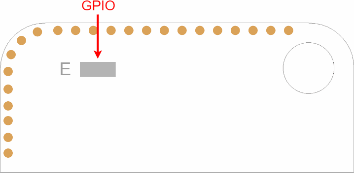
In addition, an “E” pad has been installed on the board:

This pad allows users to enable or disable the voltage output of the Veronte R12S, allowing connected subsystems to be turned ON or OFF from the Veronte Autopilot 1x GPIO outputs.
Setting the GPIO connected to “E” to LOW \(\Rightarrow\) Enables the output voltage (Vout)
Setting the GPIO connected to “E” to HIGH \(\Rightarrow\) Disables the output voltage (Vout)
Users can find information on how to create an automation in Autopilot 1x to change the status of a GPIO in the Output (Actions) - Automations section of the 1x PDI Builder user manual.
Note
This functionality is optional, it is not necessary to use it for correct operation.
Redundancy
Veronte R12S can be implemented with redundancy, so more than one R12S can be connected in parallel (with the same output voltage).
Parallel diagram
