Datalink Kit H/I - MicroHard Modem
-
First of all, to access the expansion bay, read Expansion Bay Access - Hardware Installation section of this manual.
-
Screw the brackets against the plate with two M3 x 4 mushroom bolts, so that they grip the base of the radio module.
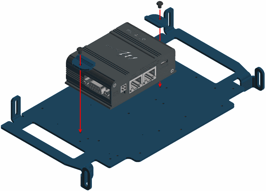
MicroHard installation - Step 2 -
Join the casing.
MicroHard installation - Step 3 -
On the opposite side of the bay; screw the amplifier with three countersunk screws M3 x 30 and apply the thermal pad.

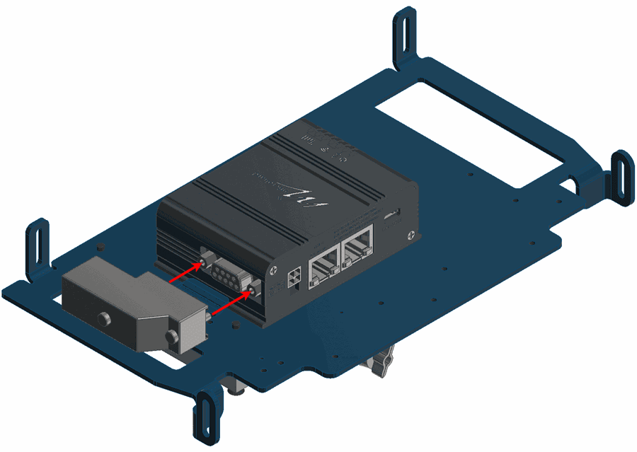
MicroHard installation - Step 4 -
Connect the modem and the amplifier as indicated by the following figure. Notice that the cable is passed through the plate hole.
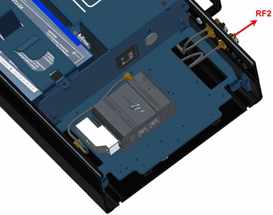
MicroHard installation - Step 5 -
Connect the amplifier to the RF2 port. Again, the cable must be passed through the indicated hole.
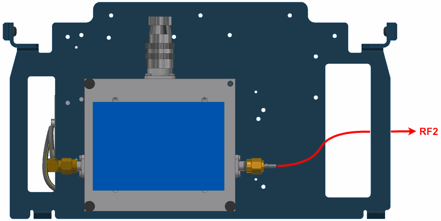
MicroHard installation - Step 6 -
Place and screw the bay plate as the following image:
MicroHard installation - Step 7 -
Connect the modem to the expansion connector.

MicroHard installation - Step 8 -
Mount the PCS to the pole according to Pole Mount Installation - Hardware Installation section of this manual (do not close the expansion bay yet).
-
Attach the omnidirectional antenna to the pole mount.
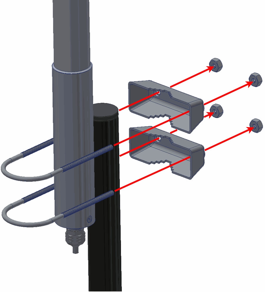
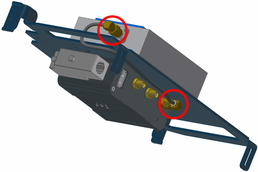
MicroHard installation - Step 10 -
Connect both antennas.
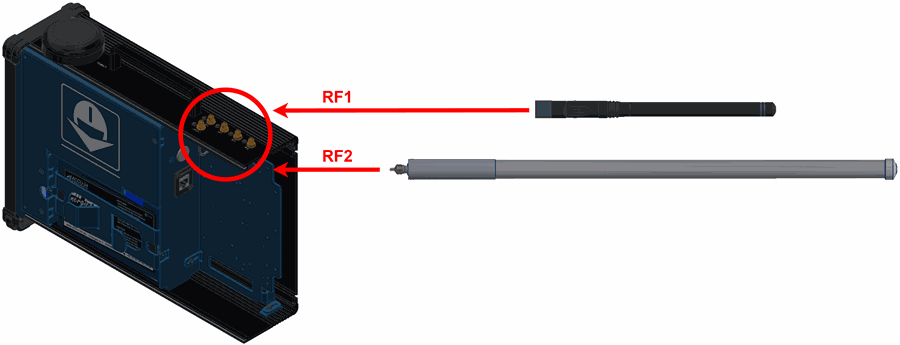
MicroHard installation - Step 11
(Diagram not scaled) -
Configure the Veronte Autopilot 1x as explained in External radios - Integration examples section of the 1x PDI Builder user manual.
-
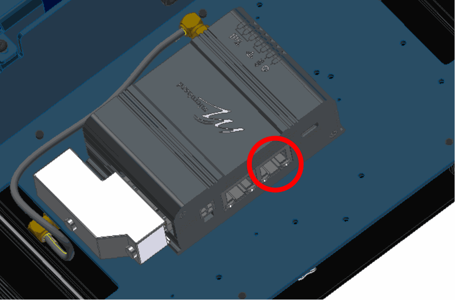
Connect the computer to the right ethernet port of the modem.
Warning
Do not connect the computer to the left port, since it is POE.
MicroHard installation - Step 13 -
To configure the modem, open a browser and introduce the following address on the search bar: 192.168.8.4.
- Calibrate the modem to the desired power.
- Once the modem and the autopilot have been configured, close the PCS.
© 2025 Embention. All rights reserved.