Datalink Kit A/B/C - Veronte SDL Modem
-
First of all, to access the expansion bay, read Expansion Bay Access - Hardware Installation section of this manual. It will not be necessary to take out the bay plate.
-
Screw the modem to the plate with four mushroom bolts M3 x 4.
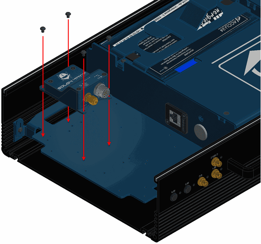
Hardware SDL installation - Step 2 -
Wire the modem to the bay connector and RF2.
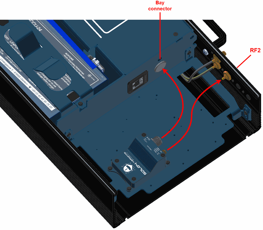
Hardware SDL installation - Step 3 -
Mount the PCS to the pole according to Pole Mount Installation - Hardware Installation section of this manual (do not close the expansion bay yet).
-
Attach the omnidirectional antenna to the pole mount.
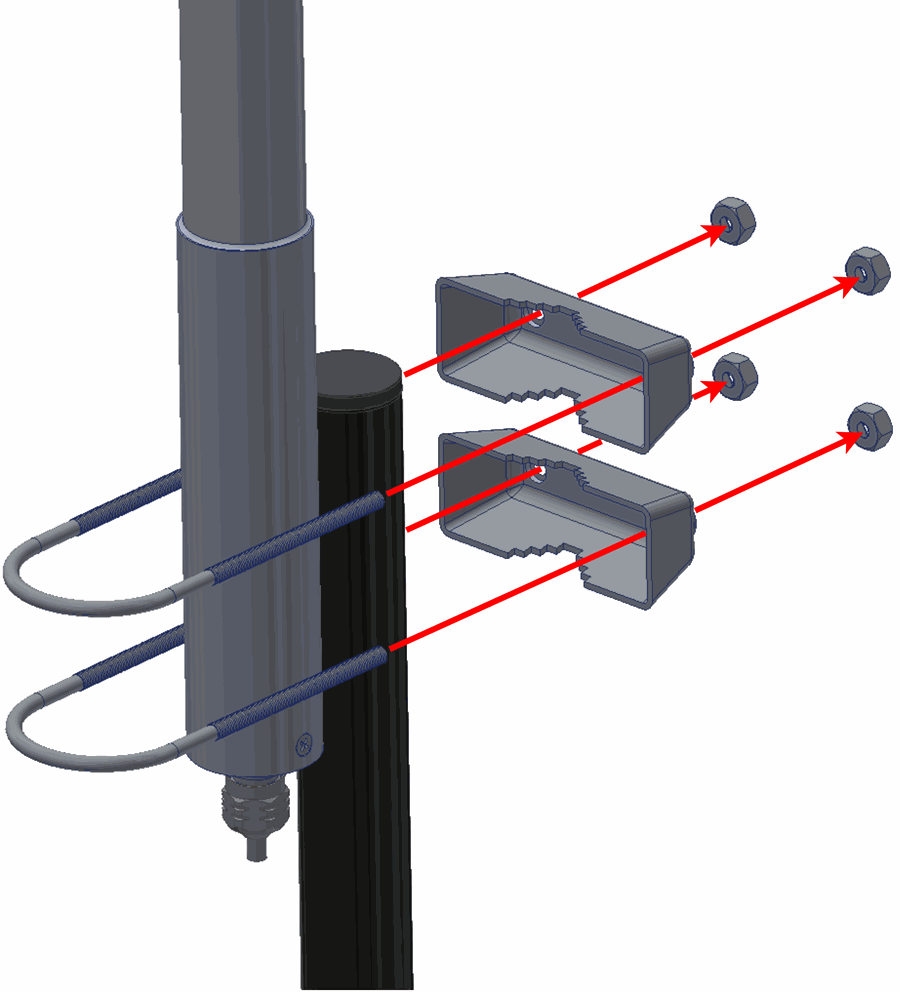
Hardware SDL installation - Step 5 -
Wire the antennas to the PCS.
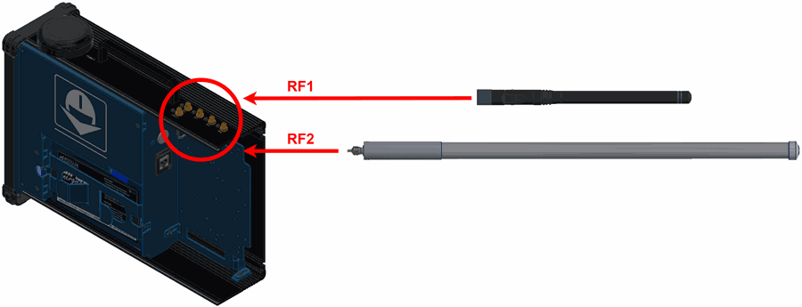
Hardware SDL installation - Step 6
(Diagram not scaled) -
Configure the Veronte Autopilot 1x as explained in External radios - Integration examples section of 1x PDI Builder user manual.
-
Configure the Veronte Autopilot 1x to communicate with SDL through a tunnel, to do it read Tunnel - Input/Output section of 1x PDI Builder user manual.
-
Once the tunnel communication is established through Autopilot 1x, the modem can be configured with AT commands.
-
To understand the basics, first of all, read How to configure SDL - Software Installation section of SDL User Manual.
-
After that, read Veronte Autopilot 1x - Integration Examples section of SDL User Manual, to configure the SDL according to the autopilot used.
-
-
Once the SDL and the Autopilot 1x have been configured, close the PCS.
© 2025 Embention. All rights reserved.