Integration examples
External Radios Included with PCS
Each PCS variant includes an external radio; then PCS requires to configure the autopilot and the radio itself.
Radio Configuration
MH radio
- Connect the computer to the ethernet cable.
- Open a browser and introduce the following address on the search bar: 192.168.8.4.
DTC radio
-
Connect the computer to the ethernet cable.
-
Make sure computer is set to static IP address on same subnet as radio. The following substeps clarify how to set the IP adress:
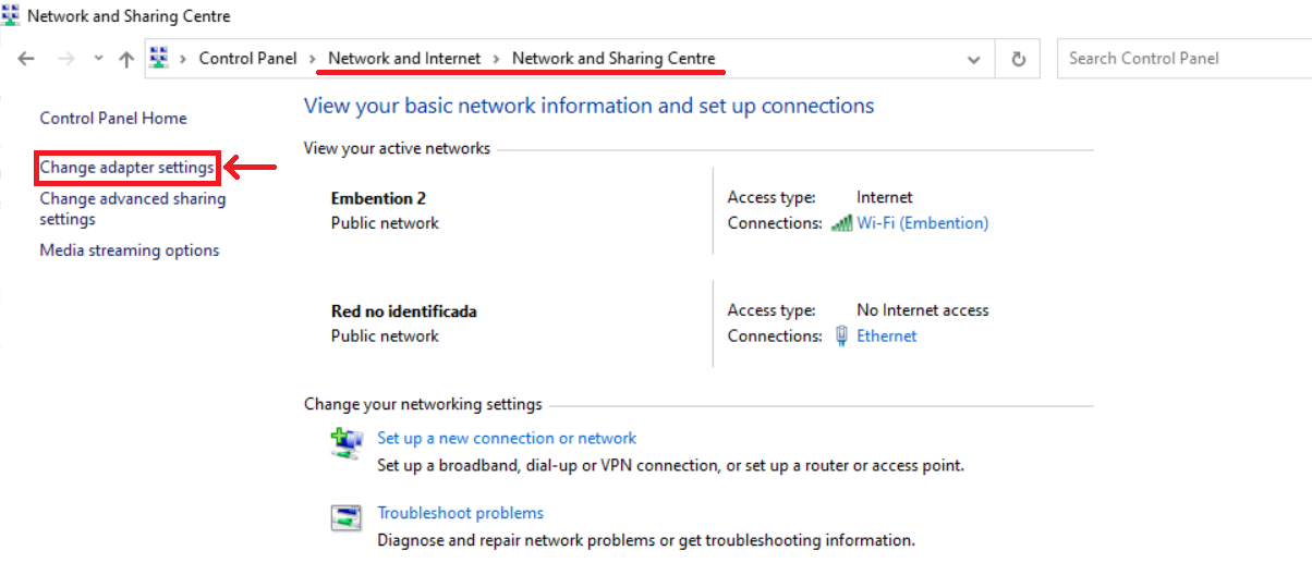
2.1. Open Network and sharing centre and click Change adapter settings.
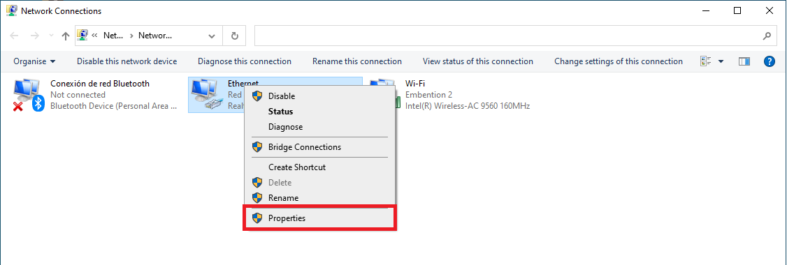
2.2 Select Local Area Connection, right click, and select Properties.
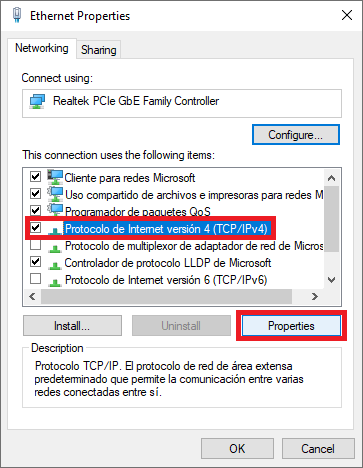
2.3 Select IPv4 and click Properties.
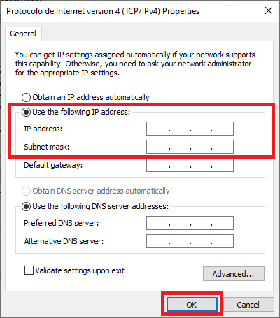
2.4 Set IP address to 192.168.8.XX; where XX is lower than 266, different of 95, 96 and every devices in the same subnet. Set the Subnet mask to 255.255.0.0 and Click OK.
-
Open a browser and introduce the radio address on the search bar 192.168.8.95.
Autopilot Configuration
-
Software version 6.4 or lowerRead the Veronte LOS section of the Veronte Autopilot user manual.
-
Software version 6.8 or higherRead the External radios section of the 1x PDI Builder user manual.
Internal Radio Configuration
This section is written for PCS that use the internal radio of the autopilot.
-
Software version 6.4 or lowerRead the Radio Pairing section of the Veronte Autopilot manual.
-
Software version 6.8 or higherRead the Digi Internal Radio section of the 1x PDI Builder manual manual.
Silvus radio (StreamCaster 4200E model)
System Layout
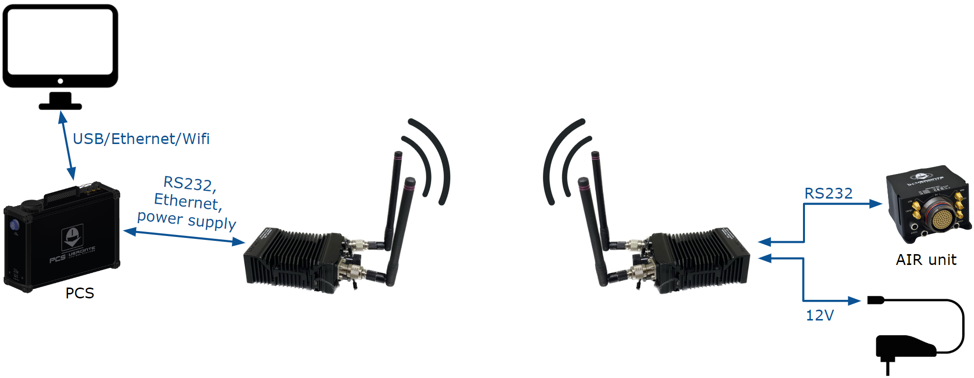
The following image shows the standard connection between Silvus radios and the PCS for operation:
Hardware Installation
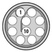
A wiring configuration of the PRI cable connected to the PRI port of the radio is required in order to connect it to the connector of the Expansion bay and the ethernet connector of the PCS.
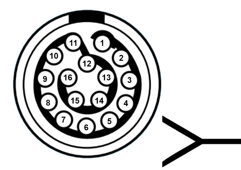
For the Expansion bay connector, the pinout is shown below:
- RS-232 and power supply
| PRI port connector - Silvus radio | Expansion bay connector - PCS | ||
|---|---|---|---|
| PIN Nº | Signal | PIN Nº | Signal |
| 2 | GND IN | 6 | GND |
| 3 | VCC IN | 5 | 12V (Output) |
| 7 | RS232_RXD | 14 | RS232-TX |
| 8 | RS232_TXD | 16 | RS232-RX |
| 9 | GND | 2 | GND |
Warning
RS-232 pins are common with the external pinnout of the PCS.
- Ethernet
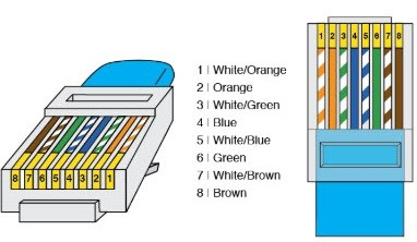
| PRI port connector - Silvus radio | RJ45 Connector (T-568B) | |||
|---|---|---|---|---|
| PIN Nº | Signal | PIN Nº | Signal | Color |
| 4 | ETH0_MX2N (RX-) | 6 | RX- | Green |
| 5 | ETH0_MX2P (RX+) | 3 | RX+ | Green-White |
| 6 | ETH0_MX1P (TX+) | 1 | TX+ | Orange-White |
| 10 | ETH0_MX1N (TX-) | 2 | TX- | Orange |
Silvus radio configuration
To know how to do a basic configuration of the Silvus radio click on:
Hardware version 4.5 or lower:Silvus Radio Configuration section of the Veronte Autopilot user manual.Hardware version 4.8:Silvus Radio Configuration section of the 1x Hardware Manual.
However, an additional configuration is required when working with a PCS instead of the GND unit of 1xVeronte autopilot.
- Networking. LAN Settings
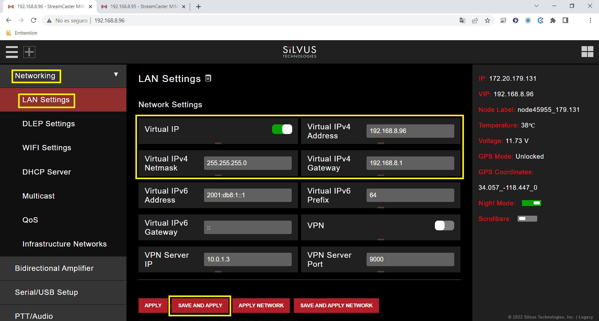
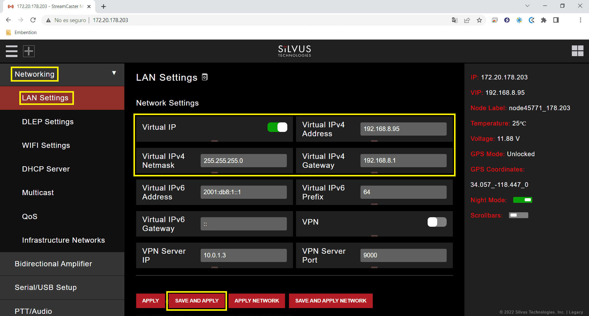
- Virtual IP: Enable or Disable the Secondary IP address for the radio. Enable
- Virtual IPv4 Address: Set the secondary IP address for the radio. The user can set any IP address, we have chosen 192.168.96 for the radio connected to the air unit and 192.168.95 for the radio linked to the PCS.
- Virtual IPv4 Netmask: Netmask for the Secondary IP address, e.g. 255.255.255.0.
- Virtual IPv4 Gateway: Gateway for local network to allow radio to connect to the internet. 192.168.8.1 is set because it is the IP address of the PCS router.
Silvus radio configuracion on PC
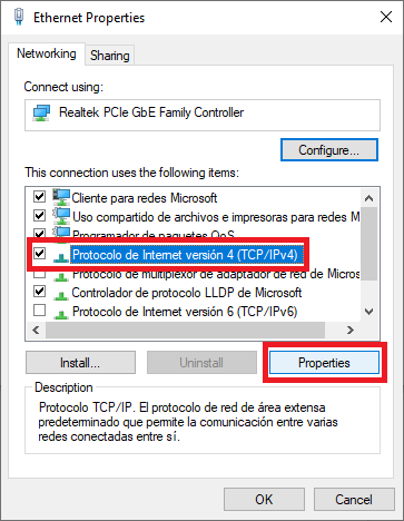
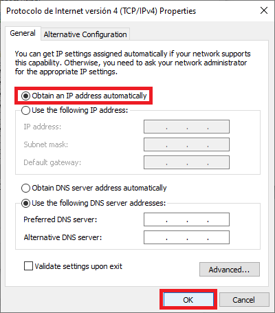
To be able to access the StreamScape GUI of the radios once connected to the PCS, check that the Network & Internet settings of the PC are as shown in the following screenshots.
Note
This configuration is the same whether the PCS is connected via wifi or ethernet.
Silvus radio configuration in autopilot
-
Software version 6.4 or lowerRead the Silvus Radio Configuration in Veronte Pipe section of Veronte Autopilot user manual.
-
Software version 6.8 or higherRead the External Radios section of the 1x PDI Builder user manual.
© 2026 Embention. All rights reserved.