Hardware Installation
Mechanical
To fix the MCx to an aircraft frame, take a look to the dimensions and screws positions in Mechanical Specifications. Screw holes must be deeper than 6 mm with M6
Electrical
Power Wiring
Warning
The input power polarity must be respected; otherwise, a short circuit may occur.
The polarity and connections are indicated in the following image and table.
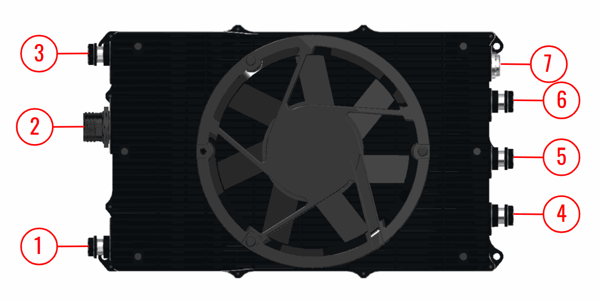
| Index | Connector | Description | |
|---|---|---|---|
| Power | 1 | HV negative | HV DC input power 100 to 800 V DC |
| 3 | HV positive | ||
| 4 | Phase U Connector | Output power to motor | |
| 5 | Phase V Connector | ||
| 6 | Phase W Connector | ||
| Electronic | 2 | User Connector | Communications, telemetry and control signals |
| 7 | Signal Connector | Encoders and sensor temperature signals |
Note
The section of the cables must be dimensioned according to the maximum power that will be used
Cable installation
Install each cable as follows:
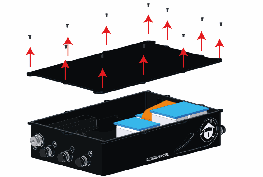
- Open the bottom enclosure. Keep the enclosure seal in place.
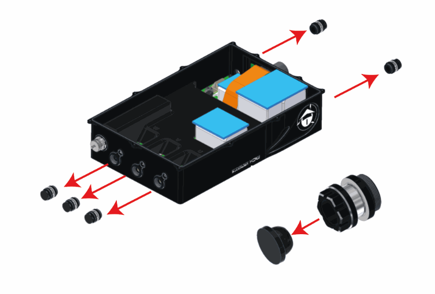
- Remove the cable gland nuts from the cable entries to be used.
- Prepare and connect the cable:
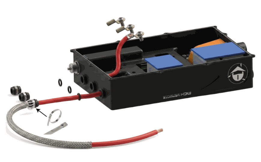
a. Install the shielding, pass the cable through the cable gland nut and O-ring, and feed it into the enclosure through the hole.
b. Crimp the cable to the cable lug.
c. Position the cable lug over its terminal by bringing the screw closer to the hole, then tighten the screw.
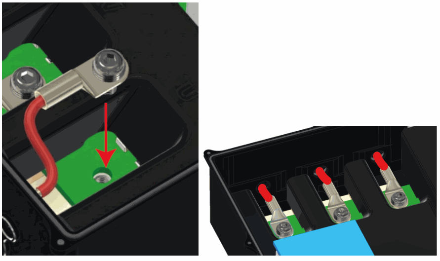
d. Tighten the cable gland nut to the enclosure and secure the cable shielding to the cable gland.
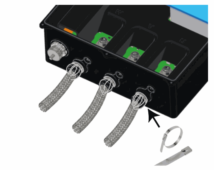
Note
Fix the cable shielding to the cable nut where the surface has no anodize protection, Using a metal clamp like the one shown in the image is recommended.
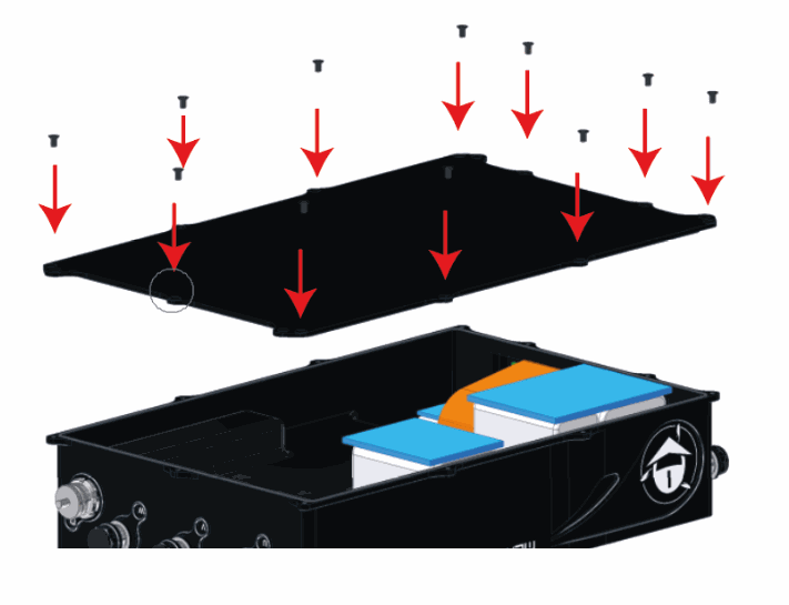
- Close the enclosure, ensuring that the enclosure seal remains correctly seated.
Pinout
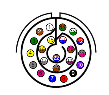
There are two pinouts: one for the User Connector and one for the Signal Connector.
User Connector
| Pin | Signal | Type | Description |
|---|---|---|---|
| 1 | IN_485_P | INPUT | RS-485 input positive |
| 2 | IN_485_N | INPUT | RS-485 input negative |
| 3 | OUT_485_N | OUTPUT | RS-485 output negative |
| 4 | OUT_485_P | OUTPUT | RS-485 output positive |
| 5 | GND | GROUND | Ground |
| 6 | CN_VIN | POWER | Positive Power Rail of the Battery |
| 7 | CN_VIN | POWER | Positive Power Rail of the Battery |
| 8 | CN_GND | GROUND | Negative Power Rail of the Battery |
| 9 | CN_GND | GROUND | Negative Power Rail of the Battery |
| 10 | GND_CAN | GROUND | Ground reference for CAN and CAN FD |
| 11 | CANFD_P | BIDIRECTIONAL | CAN FD positive pin |
| 12 | CANFD_N | BIDIRECTIONAL | CAN FD negative pin |
| 13 | GND_CAN | GROUND | Ground reference for CAN and CAN FD |
| 14 | CANB_P | BIDIRECTIONAL | CAN B positive pin |
| 15 | CANB_N | BIDIRECTIONAL | CAN B negative pin |
| 16 | GND_CAN | GROUND | Ground reference for CAN and CAN FD |
| 17 | ISO_PWM | INPUT | Positive PWM Control Input |
| 18 | FAN | OUTPUT | Output Power Signal for External Fan |
| 19 | SYNC_OUT | OUTPUT | Sync Out GPIO Signal |
| 20 | SYNC_IN | INPUT | Sync In GPIO Signal |
| 21 | HEARTBEAT | OUTPUT | Heartbeat Signal |
| 22 | Digital_GND | GROUND | Negative Power Rail of the Battery |
Signal Connector
| Pin | Signal | Type | Description |
|---|---|---|---|
| 1 | ENC_Z | INPUT | Input signal from encoder - Z |
| 2 | ENC_B | INPUT | Input signal from encoder - B |
| 3 | ENC_A | INPUT | Input signal from encoder - A |
| 4 | GND_ISO | GROUND | Isolated negative power rail |
| 5 | ISO_TEMP | INPUT | Motor temperature sensor |
| 6 | +1V | POWER | +1 V isolated voltage supply |
| 7 | GND_ISO | GROUND | Isolated negative power rail |
| 8 | +5V | POWER | +5 V isolated voltage supply |
| 9 | +5V | POWER | +5 V isolated voltage supply |
| 10 | ENC_COS | INPUT | Cosine signal from SinCos encoder |
| 11 | ENC_SIN | INPUT | Sine signal from SinCos encoder |
| 12 | GND_ISO | GROUND | Isolated negative power rail |
| 13 | GND_ISO | GROUND | Isolated negative power rail |
| 14 | GND_ISO | GROUND | Isolated negative power rail |
| 15 | GND_ISO | GROUND | Isolated negative power rail |
| 16 | GND_ISO | GROUND | Isolated negative power rail |
Compatible Connectors
The following connectors are compatible with the User and Signal Connectors.
| Compatible with | Connector | Description | Embention Reference |
|---|---|---|---|
| User Connector | Veronte Motor Controllers: Dev Harness MCX 2.2 | Development harness with connectors. | P012537 |
| Veronte Harness - 22P MIL-DTL-38999 - Male - 50 cm | Amphenol connector with loose wires for aircraft integration. | P016323 | |
| Signal Connector | Veronte Connector 16P | LEMO connector with crimp contacts for aircraft integration. | P006993 |
User Connector Harnesses
Dimensions
- Cables length: 50 cm
Pinout
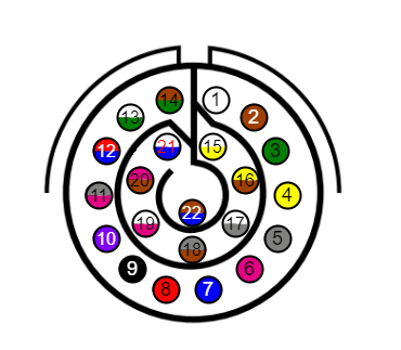
Veronte Harness - 22P MIL-DTL-38999 - Male - 50cm
The pinout of the Veronte Harness is the same as the pinout above. The color code of the harness wires is given below.
| Pin | Color code | Pin | Color code |
|---|---|---|---|
| 1 | White | 12 | Red - Blue |
| 2 | Brown | 13 | White - Green |
| 3 | Green | 14 | Brown - Green |
| 4 | Yellow | 15 | White - Yellow |
| 5 | Gray | 16 | Yellow - Brown |
| 6 | Pink | 17 | White - Gray |
| 7 | Blue | 18 | Gray - Brown |
| 8 | Red | 19 | White - Pink |
| 9 | Black | 20 | Pink - Brown |
| 10 | Violet | 21 | White - Blue |
| 11 | Gray - Pink | 22 | Brown - Blue |
Veronte Motor Controllers: Dev Harness MCX 2.2
The pinout of this harness is the same as the pinout above. In addition, this harness has some connectors already implemented for easy operation. Below is detailed information on which pins these connectors are connected to:
| Connector | PIN | Signal |
|---|---|---|
| RS-485 | 1 | IN_485_P |
| 2 | IN_485_N | |
| 3 | OUT_485_N | |
| 4 | OUT_485_P | |
| 5 | GND | |
| Power Input | 6 and 7 | CN_VIN |
| 8 and 9 | CN_GND | |
| Maintenance button | 19 | SYNC_OUT |
| 20 | SYNC_IN |
Electrical Diagram of CAN Bus
Like any other CAN device, Veronte MCx requires a termination resistor to allow the connection of multiple MCxs or other CAN bus devices to the same line. For this termination resistor, users can add an external resistor or simply activate the 120 resistor that MCx has internally (this is activated via software).
Below are some of the different configurations according to users preference.
Important
The scenarios described below are provided as examples of common setups. Users are free to implement custom wiring configurations that best suit their vehicle's design.
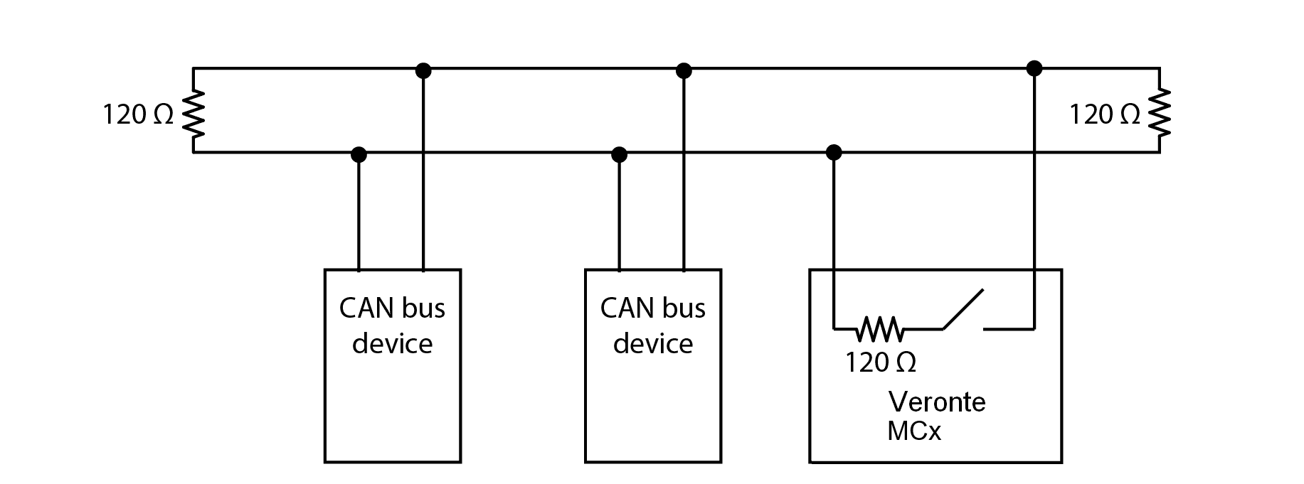
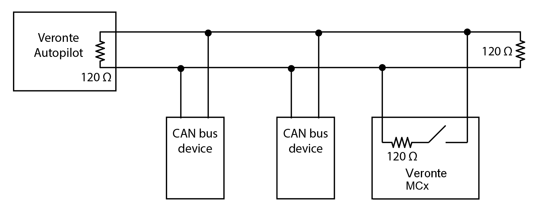
The critical principle for any valid setup is that the CAN bus line must be terminated with a 120 Ω resistor at its two physical ends: one at the beginning and one at the end. As long as this rule is followed, any combination of internal or external resistors may be used.
In this setup, the MCx's internal resistor is not used. Instead, two external 120 resistors are placed at the physical ends of the CAN bus to provide termination. The MCx can be located anywhere on the bus, including at the end, but its internal resistor must remain disabled in the software.
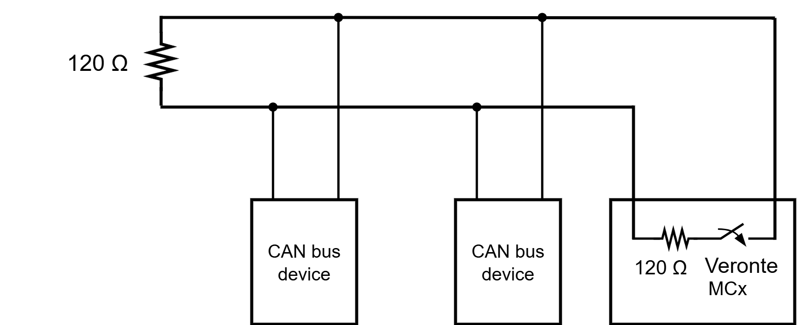
This configuration uses the MCx's built-in termination feature for one end of the bus. The Veronte MCx is placed at one physical end of the line, and its internal 120 resistor is enabled via software. A single external 120 resistor is then installed at the opposite end of the bus to complete the termination.
Considering Veronte Autopilot includes one entrance resistor of 120 , for the simplest wiring, this configuration uses the internal resistors of both the Veronte Autopilot and the Veronte MCx. The Veronte Autopilot, which includes a 120 resistor, is placed at one end of the bus. The Veronte MCx is placed at the other end, and its internal 120 resistor is enabled via software. This setup provides full bus termination without requiring any external components.
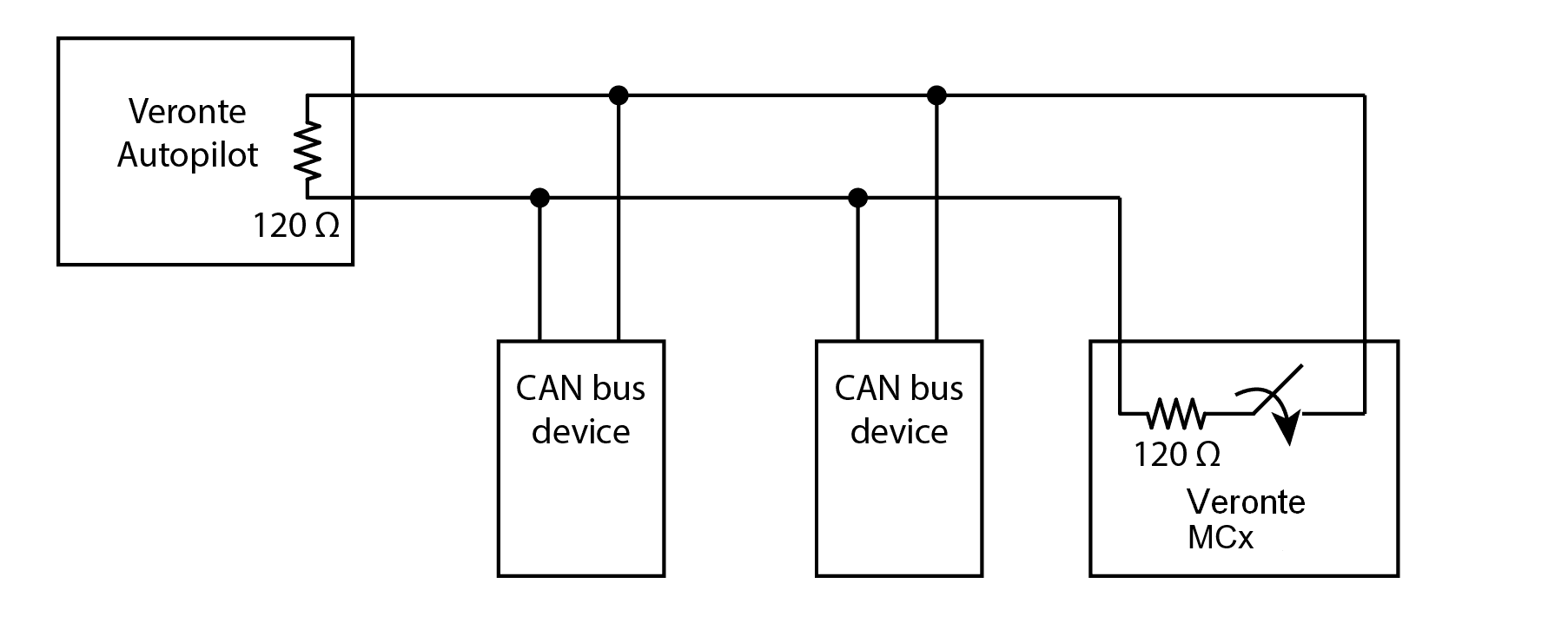
In this latter case, the 120 internal resistor of the Veronte Autopilot is placed at one end of the bus and an external 120 resistor is installed at the end of the CAN bus, leaving the internal resistor of the Veronte MCx disabled, as shown in below:
© 2026 Embention. All rights reserved.