 MC
MC
Open Loop Startup
If it is not possible to start-up with the low speed PLL observer, it could be done by the open loop procedure:
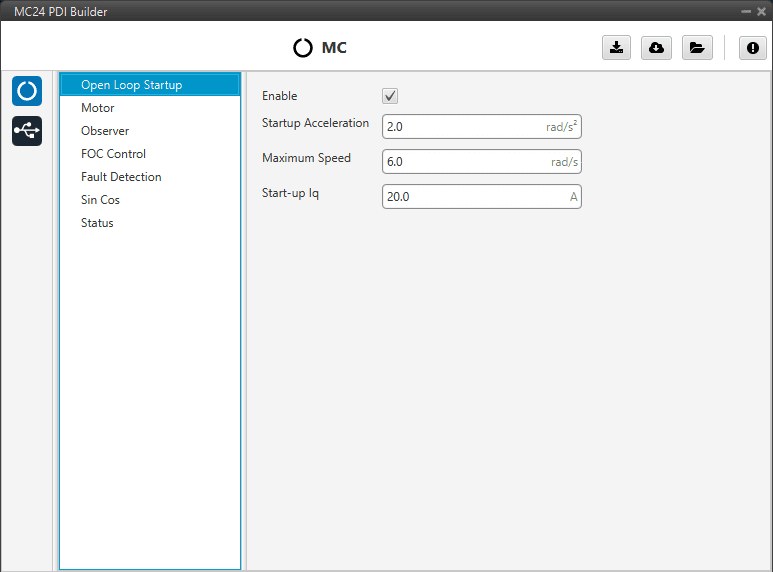
Open Loop Startup section
In this panel the parameters for open-loop start-up are configured:
Enable: Enables the open-loop start-up.
Startup Accelaration: This is the slope of the start ramp. It is usually a value that allows for a 1-2 second start-up.
Maximum Speed: Maximum speed reached on the start ramp. It is usually approximately 10-15% of the maximum speed of the mechanical motor.
Start-up Iq: Since the speed controller is not working at this point, it is necessary to command a current \(I_{q0}^{*}\) to start the motor. This current is constant, and moreover, it is all active current \(I_q\) (of torque).
As the user always wants to maximize the torque, the commanded reactive current \(I_{d}^{*}\) is zero. At constant speed, the higher this value, the more torque the motor will have at start-up. It is usually about 10% of the maximum \(I_q\) value.
Motor
This tab sets all the electrical/mechanical parameters of the motor that will define the controller dynamics.

Motor section
Stator internal resistance: This is the line-to-neutral resistance of the motor. Here it is necessary to take into account the harness resistance if it is not negligible. Expressed in Ohms (\(\Omega\)).
Quadrature/Direct Inductance: Line-to-neutral motor inductance in q-d axes. Expressed in Henries (\(H\)).
Pole Pairs: The number of pole pairs shall allow calculation of the mechanical speed of the motor.
Maximum RPM: Maximum desired mechanical speed that the motor can reach. It allows to calculate the input rate in terms of desired speed.
This parameter is only used to determine the equivalence between the maximum command (PWM or CAN) and the commanded RPM in speed closed loop mode.
Maximum Iq: Maximum permissible quadrature current that the motor can drive.
Maximum Id: Maximum allowable direct current that the motor can conduct. Only used in the MTPA/FW scheme.
Back-EMF constant: This is the line-to-neutral Back-EMF constant. Expressed in \(\large \frac{V}{rad/s}\).
Total Moment Of Inertia (MOI): Total moment of inertia (motor + load). Expressed in \(kg \cdot m^2\).
Note
Back-EMF constant is an important parameter for low-speed PLL observer, so a correct characterization of this parameter will allow control in the low-speed range and start-up without open-loop procedure.
Observer
The algorithm is prepared to work with two observers (low and high speed observer) working in a predefined speed range.
Moreover, there are two low-speed observers that can be selected: PLL observer and Arc-tangent observer (this should be configured in the FOC Control section). The first one allows starting without open loop while the second is usually selected when there is an open loop procedure.
The observer mixing limits [low,up] are usually approximately 2% and 15% of the maximum mechanical speed.
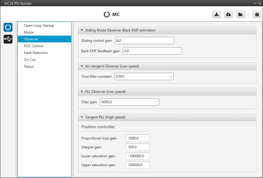
Observer section
Here the observers parameters must be configured:
Sliding Mode Observer (Back-EMF estimator): Sensor-less estimator for the Back-EMF.
Sliding Control Gain: This is the main gain of the observer.
To ensure the stability of the algorithm, this value must be greater than the absolute value of Back-EMF on the alpha/beta axes.
Back-EMF feedback gain: This value is to account for unfiltered Back-EMF. It should be between 0 and 1.
Arc-tangent Observer (Low speed): It is one of the low speed position observers.
Time filter constant: This is the time constant of the first order filter of the speed calculation. The lower value, the lower filtering.
PLL Observer (Low speed): It is the second one low speed position observer.
Filter gain: Filter cutoff frequency.
Note
Users can choose one of the two low-speed observers (arc-tangent or PLL) by selecting it in the low speed observer parameter of the FOC control menu.
Tangent PLL (High speed): This is the high speed position observer. It is controlled by a PI control.
Warning
It is recommended to tune this estimator even if an external sensor is used for feedback (sensored control).
As it will be described in the next section, the control will automatically jump in case the primary feedback source fails to a sensorless control.
FOC Control
First, the PI (Proportional and Integral) controller is presented.
The form of the PI is the classical parallel form:
Where integral gain refers to the quotient \(\Large \frac{1}{T_i}\). Lower and upper saturation gain are the limits to which the PI limit its output.
FOC Control is the main control menu, where all parameters related to FOC control are set.
The basic blocks that define the FOC control are three PI control loops that should be tuned with the motor characterization.

FOC Control section
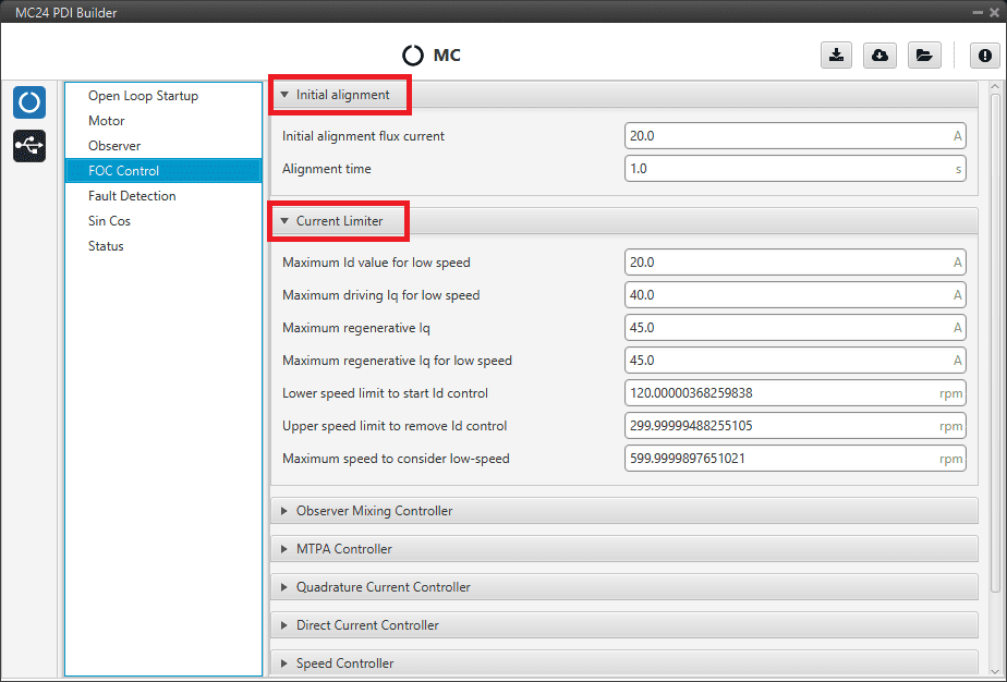
FOC Control - Initial alignment and Current Limiter parameters
Note
These default parameters should work correctly.
Initial alignment: Start-up initial alignment procedure.
If the detection of the initial rotor position is not available or is difficult to obtain, it is desirable to lock the rotor to a known state (usually zero angle) at start-up. This procedure allows the rotor to always be aligned in the same electrical position.
Note
This part of the configuration is essential if the open-loop is disabled.
Initial alignment flux current: This is the desired \(I_d\) current to align the rotor. It should be about 15% of the maximum phase current of the motor.
Alignment time: This is usually about 1 second.
Current Limiter: Limiter block for the desired currents \(I_q\) and \(I_d\).
Maximum Id value for low speed.
Maximum driving Iq for low speed.
Maximum regenerative Iq.
Maximum regenerative Iq for low speed.
Lower speed limit to start Id control.
Upper speed limit to remove Id control.
Maximum speed to consider low-speed.
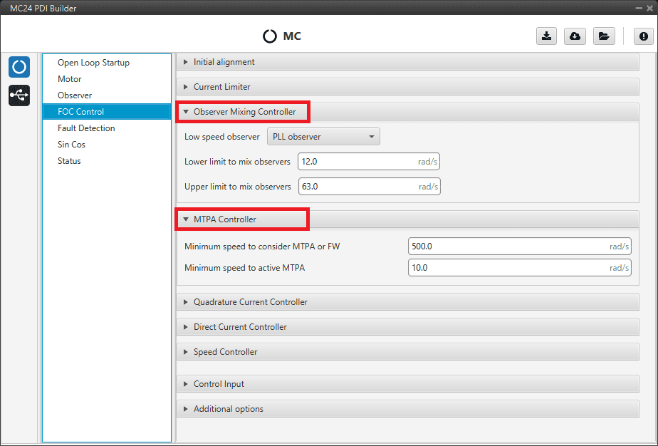
FOC Control section - Observer Mixing Controller and MTPA Controller
Observer Mixing Controller: Definition of the range of low-high speed observers.
Low speed observer: Users should select the low-speed observer to be used: arc-tangent or PLL.
Lower limit to mix observers.
Upper limit to mix observers.
MTPA Controller: Maximum Torque Per Ampere controller.
It is used to reach a higher speed than the base speed of the motor. In addition, it can work in a Field Weakening to control with \(I_d\).
Minimum speed to consider MTPA or FW.
Minimum speed to active MTPA.
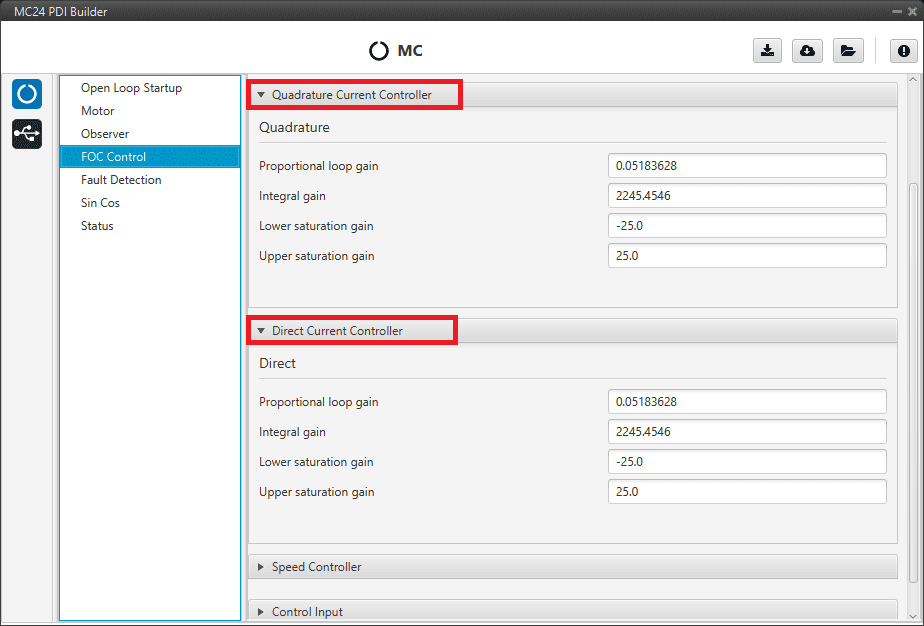
FOC Control section - Quadrature Current Controller and Direct Current Controller
Both quadrature and direct current PI control must be defined. Also, the quadrature and direct PI gain settings are usually the same, but it will depend on whether the motor parameters are the same on both axes.
Quadrature Current Controller: Torque regulator. It is controlled by a PI control.
Direct Current Controller: Flux regulator. This is controlled by a PI control.
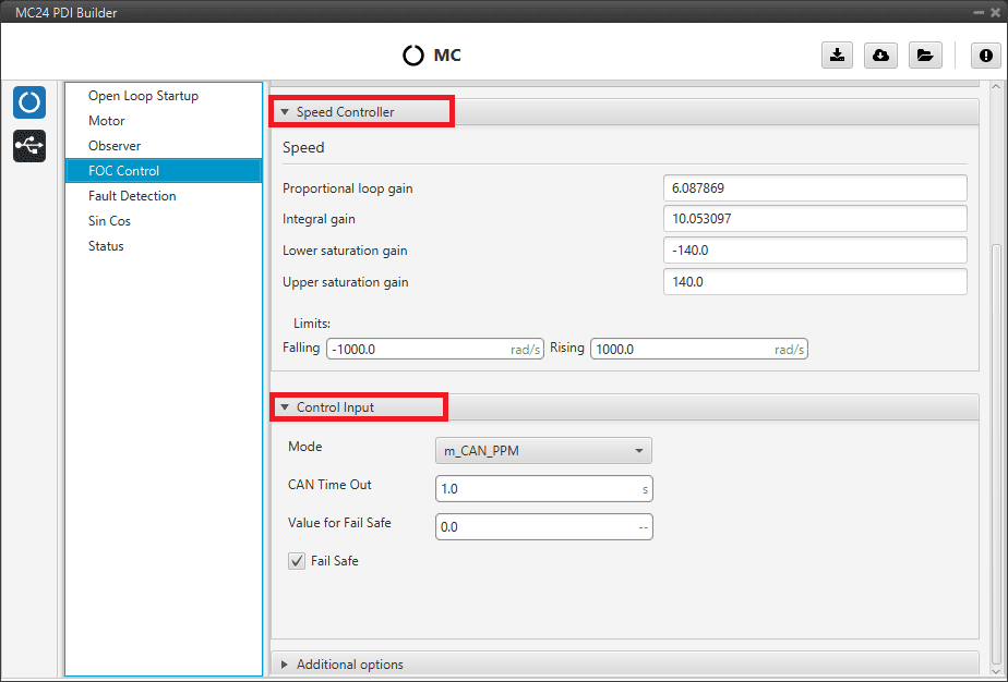
FOC Control section - Speed Controller and Control Input
Speed Controller: It is controlled by a PI control.
Limits: Maximum desired motor acceleration.
Falling: Decceleration rate. Expressed in \(rad/s^{2}\).
Rising: Acceleration rate. Expressed in \(rad/s^{2}\).
Control Input: Control input allows the user to select the input source and several additional parameters such as:
Mode: Control mode. The available options are m_PPM, m_CAN and m_CAN_PPM.
CAN Time Out: Whenever this timeout is met, the control input will switch to the next option if available. If none of them are available, it shall end up in failsafe mode.
Value for Fail Safe: Value between 0 and 1. To be written in case the previous mode options are not available.
Fail Safe: Activates failsafe mode.
The input flow is the following in case the mode m_CAN_PPM is selected:

CAN_PPM mode diagram
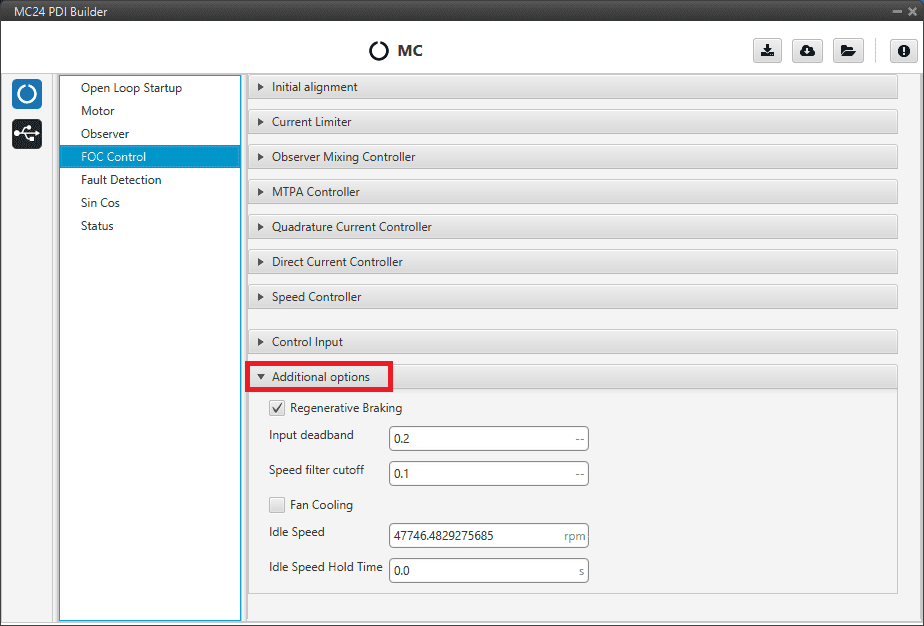
FOC Control section - Additional options
Additional options:
Regenerative Braking: Activates regnerative braking feature which is basically consisting of thoughing negative current back to battery whenever the motor is loosing speed (it uses the kinetic energy to charge de battery).
If disabled, it will only allow slow down due to losses.
Warning
Activating this option is only recommended with batteries (charging them when braking), but not with a power supply, as they are not prepared to receive current (it is necessary to activate the sink mode to work with it).
Input deadband: This is the value of the input rate at which the motor will start to move.
For example, it may be desired to be non-zero in case an RC stick outputs about 0.2 duty cycle by default.
Note
In case CAN Bus is used to command (see CAN I/O section), this deadband can be calculated as \(\large \frac{RPM^*}{RPM_{max}}\).
Speed filter cutoff: Cutoff frequency (expressed in Hz) to be applied only to Hall effect sensors and SIN/COS sensors filters.
Fan Cooling: This option activates a PID control on a cooling fan to reach normal operating temperature.
Idle Speed: Minimum motor speed for switching OFF.
If an input rate lower than the input deadband is commanded, until this speed is reached (idle speed), the MC24 shall not switch to OFF mode.
Idle Speed Hold Time: After the above conditions have been met (speed lower than idle speed) and this time (idle speed hold time) has elapsed, the MC24 shall switch to off mode.
This is done to avoid operator input rate errors.
Finally, the following state machine will be executed:

State machine diagram
Fault Detection
Active-passive fault management. There are two types of failures:
Critical fault: It will be followed by a latched OFF state.
Non Critical fault: It will be only followed by a warning.
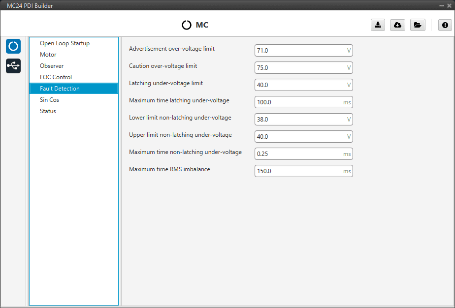
Fault Detection section
Advertisement over-voltage limit: Non Critical fault.
Caution over-voltage limit: Non Critical fault.
Latching under-voltage limit: Critical fault.
Maximum time latching undel-voltage.
Lower limit non-latching under-voltage: Non Critical fault.
Upper limit non-latching under-voltage: Non Critical fault.
Maximum time non-latching under-voltage.
Maximum time RMS imbalance: Critical fault.
Note
There are more fault detections but cannot be configured because it depends on the limits of the ESC.
Sin Cos
In case it is necessary to use an external SIN/COS sensor as a source of electrical angle/speed feedback, the main interface for doing so is via ADC inputs.
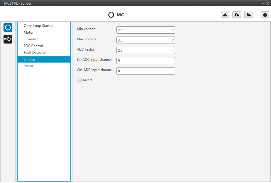
Sin Cos section
This menu allows the user to customize the main characteristics of his sensor:
Min Voltage: Minimum signal voltage. Measured in Volts (V).
Max Voltage: Maximum voltage of the signal. Measured in Volts (V).
ADC factor: Factor that multiplies the ADC port reading, especially useful if a voltage divider (or any other signal level adapter) is installed.
Sin ADC input channel: ADC channel to which the Sin signal is connected.
Cos ADC input channel: ADC channel to which the Cos signal is connected.
Invert: Inverts the resulting electrical angle. Useful for correcting installation inversions.
Status
Enable VCP Status Message enables the periodic sending of the status message that Veronte Link uses to recognise the Veronte Motor Controller MC24.
Period: Enter a desired period to send repeatedly the status message.

Status section
Note
VCP is the Veronte Communication Protocol. To know more, read the VCP user manual.
