 Control
Control Brushless
First, the PI (Proportional and Integral) controller is presented.
The form of the PI is the classical parallel form:
Where:
\(K_p\) is the Proportional loop gain.
Integral gain refers to the quotient \(\Large \frac{1}{T_i}\).
Lower and Upper saturation gain are the limits to which the PI limit its output.
Control Brushless is the main control menu, where users must enter the control parameters according to their motor.
The basic blocks that define the control are four PI control loops that should be tuned with the motor characterization.
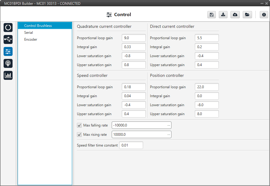
Control Brushless section
Both quadrature and direct current PI control must be defined. Also, the quadrature and direct PI gain settings are usually the same, but it will depend on whether the motor parameters are the same on both axes.
Quadrature current controller: Torque regulator. It is controlled by a PI control.
Direct current controller: Flux regulator. This is controlled by a PI control.
Speed controller: It is controlled by a PI control.
Position controller: It is controlled by a PI control.
Maximum desired motor acceleration:
Max falling rate: Deceleration rate. Expressed in \(rad/s^{2}\).
Max rising rate: Acceleration rate. Expressed in \(rad/s^{2}\).
Speed filter time constant: This is the time constant of the first order filter of the speed calculation. The lower value, the lower filtering.
The time constant is approximately defined as:
\[\tau = \frac{1}{2 \; \pi \; f_{c}}\]Where:
\(\tau\): time constant
\(f_{c}\) : cutoff frequency
Serial
MC01B can only use one serial peripheral, SCIA port, the serial parameters that fit the serial protocol requirements can be edited in this menu:
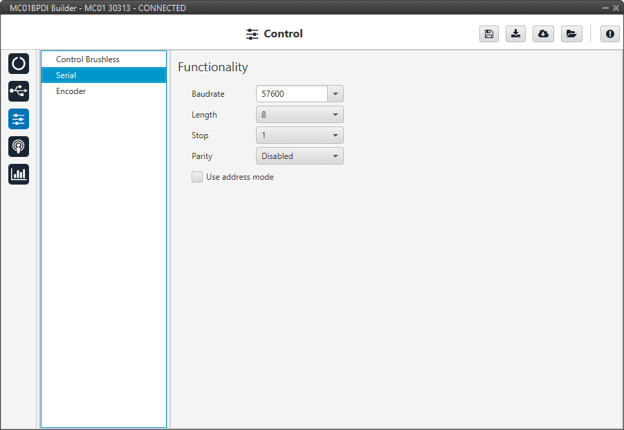
Serial section
Baudrate: This field specifies how fast data is sent over a serial line.
Length: Defines the number of data bits for each character: 4 to 8 bits.
Stop: Number of stop bits sent at the end of each character: 1, 1.5 or 2.
Parity: Method to detect errors during transmission. When parity is used with a serial port, an extra data bit will be sent with each data character.
The bits of each character (including parity bit) will be even or odd according to parity mode (odd, even or disabled).
Use address mode: 9-bit data framing uses the bit typically associated with parity error detection to identify address messages. Sent serial data that does not have the address bit set will be ignored (unless the device had previously identified an address message associated with it).
This option can be disabled or enabled.
Encoder
In this section, the user must define the number of bits employed by the encoder to communicate the position of the motor.
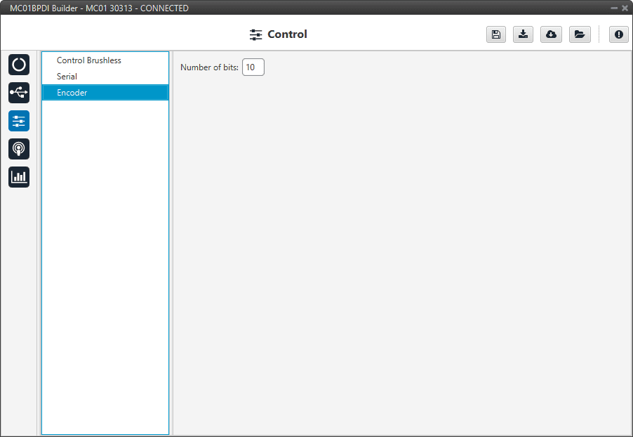
Encoder section