Hardware Installation
The Joystick 16CH does not require any hardware installation to operate with its own integrated antenna. Nonetheless, to operate with the Veronte system (PCS + T28 + Antenna kit), the following installation is required.

Veronte system diagram
The integration of T28 in PCS is explained in the Hardware Installation section of the T28 Hardware Manual.
The hardware installation for each Antenna kit can be read in the Tracker Antenna Kit Installation - Integration Examples section of the T28 Hardware Manual.
Joystick 16CH and PCS can be connected plugging the CAN bus connector of the PCS harness to the CAN bus port of the Joystick 16CH.
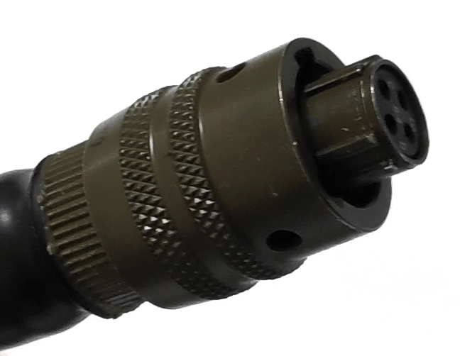
CAN bus connector of PCS harness
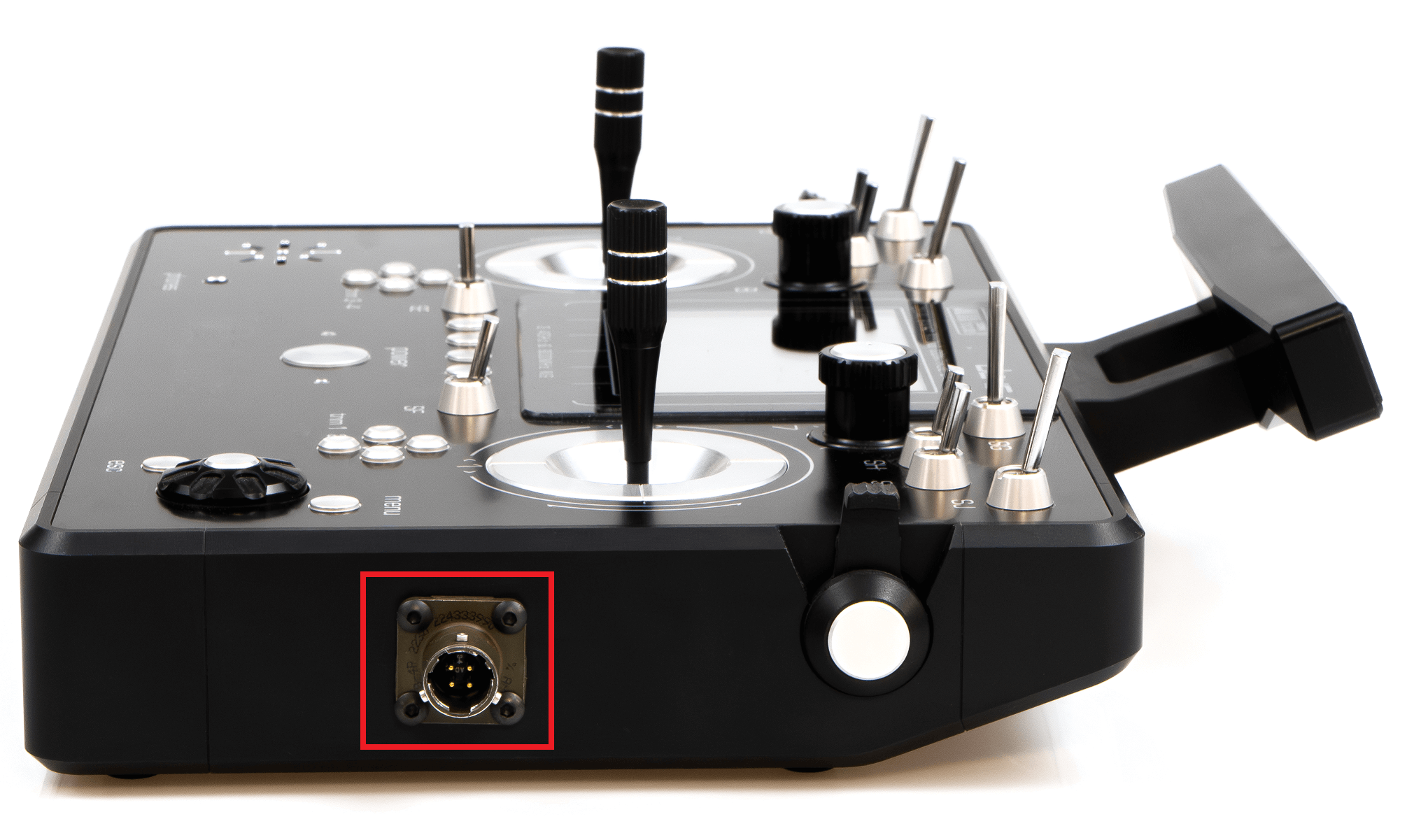
CAN bus port of Joystick 16CH
Pinout
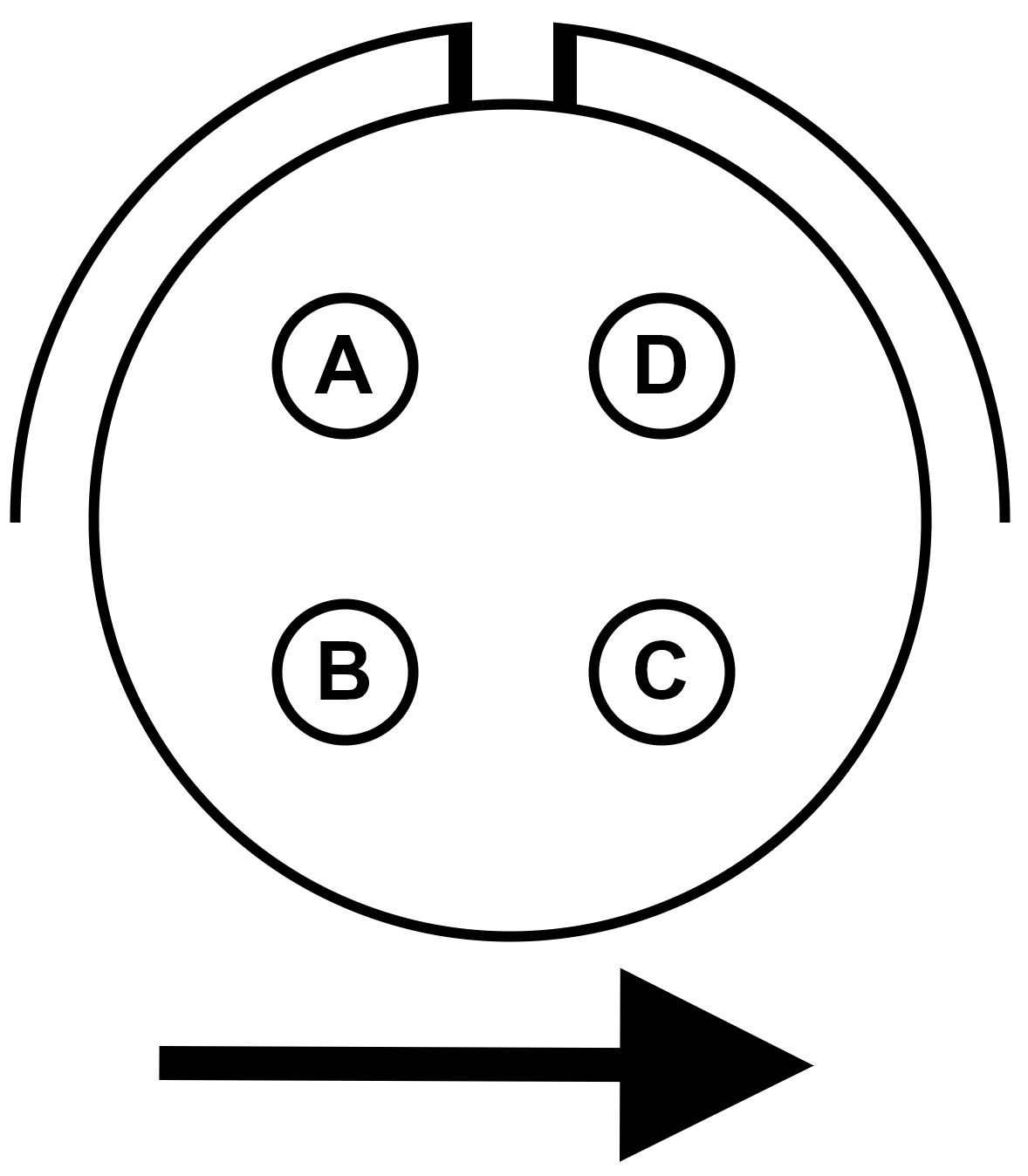
CAN bus port of Joystick 16CH
Pin |
Signal |
Comments |
|---|---|---|
A |
Power supply |
Power supply for the controller. |
B |
Ground |
Ground for the CAN bus controller. |
C |
CAN P |
High signal of the CAN bus. |
D |
CAN N |
Low signal of the CAN bus. |
ADVANCED TIP
The CAN communications of Joystick 16CH are managed by an internal MEX module. The CAN port is connected directly to MEX as follows:
CAN bus port pin |
MEX pin |
|---|---|
A |
1 & 3 |
B |
2 & 4 |
C |
22 |
D |
23 |
To know each function of the MEX pinout, read the Pinout - Hardware Installation section of the MEX Hardware Manual.
To establish communication between a computer and MEX, it is recommended to do through a CAN tunnel with an Autopilot 1x. To do it, read CEX/MEX - Integration examples section of 1x PDI Builder user manual.
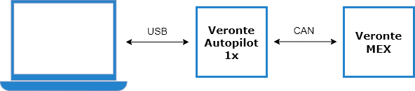
Tunnel connection through Autopilot 1x
Once the connection has been established, the internal MEX can be configured with MEX PDI Builder.