Operation
To start using HIL Simulator, follow the next steps:
-
Connect the autopilot to a computer and establish the connection through Veronte Link.
Note
Read the Veronte Link user manual for more information.
-
Open HIL Simulator and wait a few seconds for the connected autopilot to be detected.
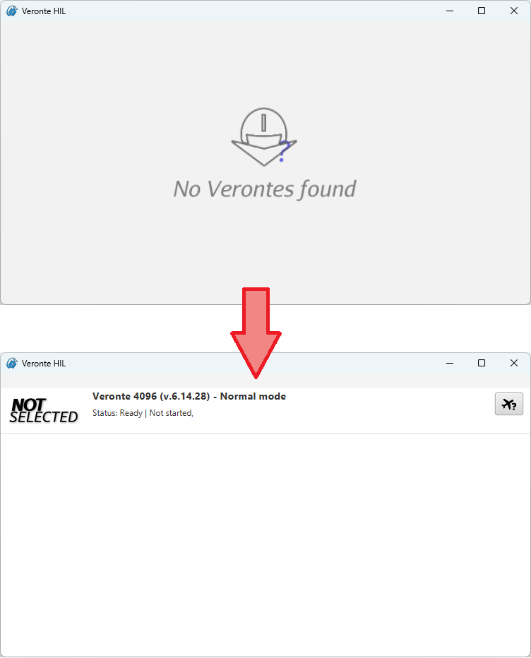
HIL detection of connected autopilot Note
HIL will now run minimized in the System Tray:

Minimized running Once the autopilot has been detected, HIL Simulator will display the following menu:
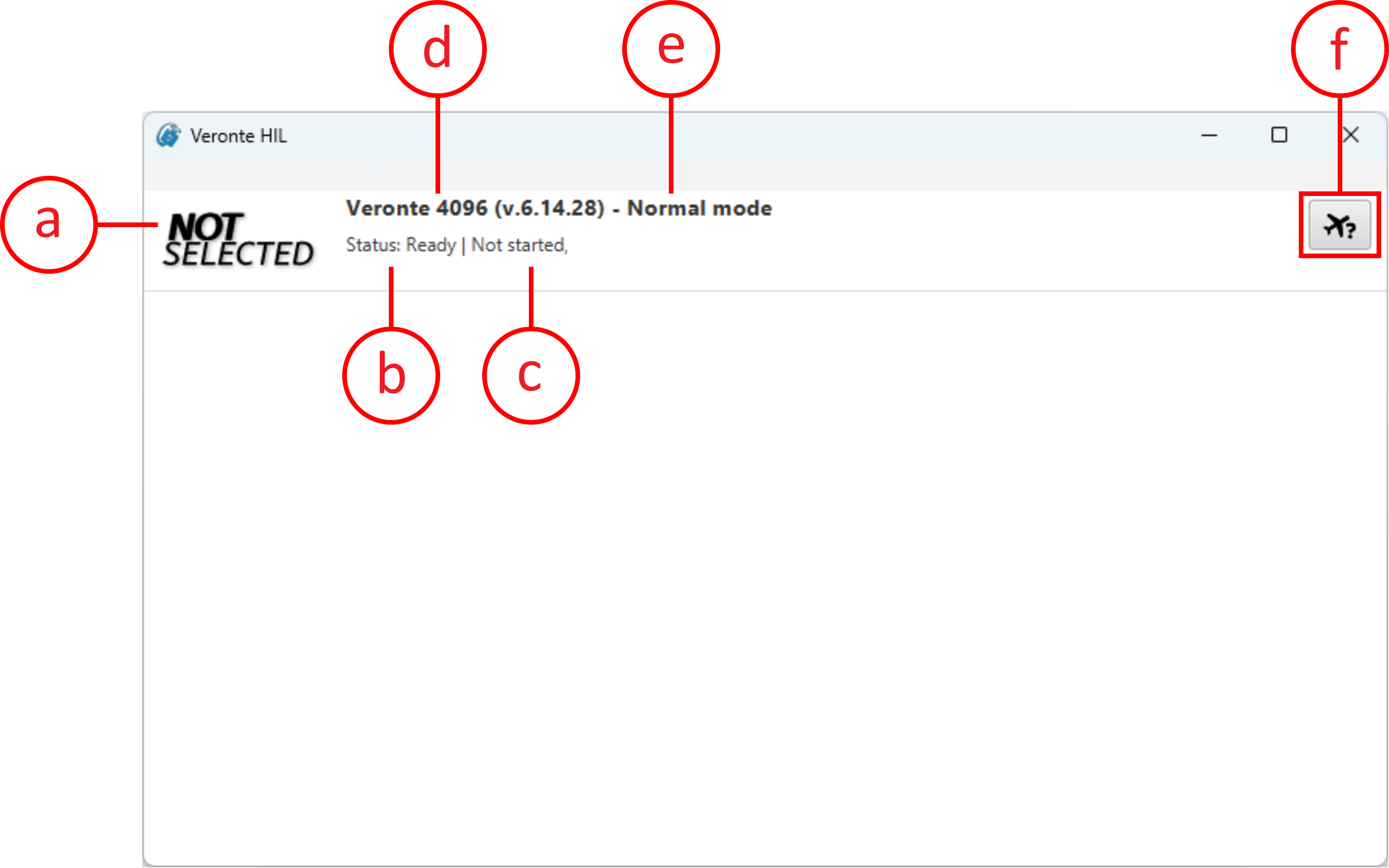
HIL Simulator - Main menu a. Simulator icon: The icon of the selected simulator is displayed.
b. Status of the autopilot: Ready, Running, Failed load conf, Maintenance mode or Offline.
c. Status of the simulation:
- Not started.
- Once started, simulation frequency parameters are displayed.
- To Simulator: Frequency of data transmission to the external simulator selected.
- To Platform: Frequency of data transmission to the autopilot.
d. Autopilot ID and firmware version
e. Autopilot mode
Important
The autopilot must be in Normal Mode to start the simulation. Refer to Unable to start HIL Simulation - Troubleshooting section of this manual for further details.
f. Select simulator button
This menu presents slightly different features when a Veronte Autopilot 4x is connected:
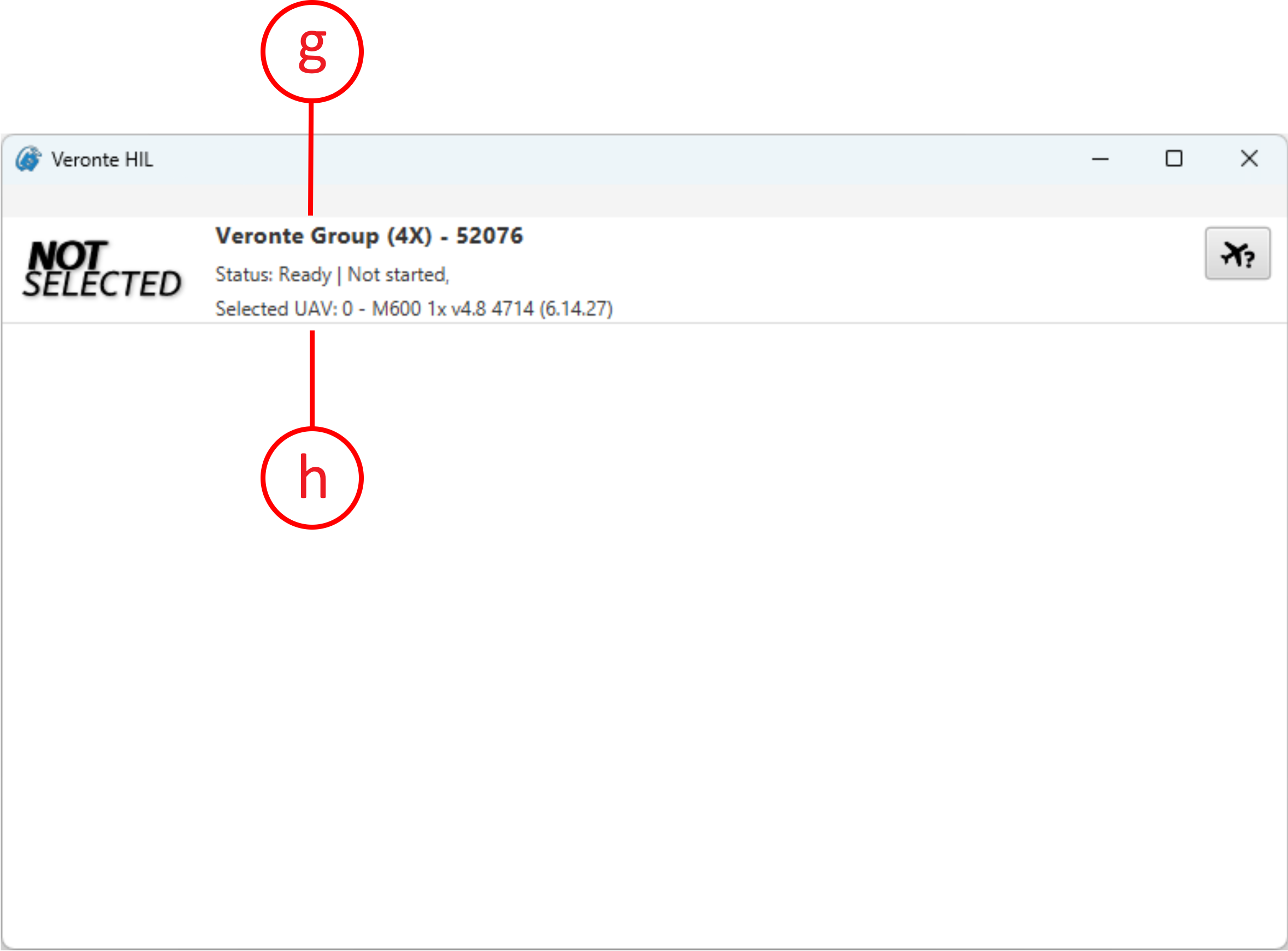
HIL Simulator - Main menu for 4x g. Autopilot 4x name: 4x is labeled as "Veronte Group (4x)" and its ID.
h. Selected UAV: The index of the Autopilot 1x selected by the arbiter and its unit name are displayed.
Note
The ‘Status’ displayed when connecting a 4x corresponds to the status of the selected UAV.
-
Choose a simulator.
Click on
 to choose a simulator to conduct HIL simulation.
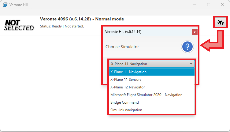
-
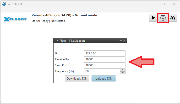
Configure HIL simulation parameters (optional).
Default configuration parameters are recommended. To change them, click on
 .
.
Note
Some additional parameters may be configurable depending on the selected simulator.
-
Configure the simulation parameters in the selected simulator software.
The selected simulator must be configured with the same IP, port and frequency as HIL Simulator.
Note
The procedure to configure these parameters vary depending on the simulator, consult the subsequent sections for more information.
-
Run the selected simulator software.
-
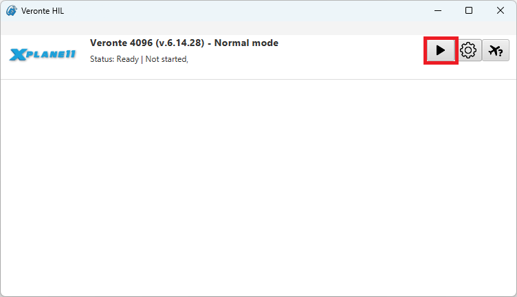
Start HIL Simulator.
Navigation variables
Variables of navigation must be shared between external simulators and Autopilot 1x for a functional simulation.
For this reason, with a proper configuration of HIL Simulator settings, the following variables are automatically sent to 1x:
Note
For further information on these variables, please consult the Real variables list of the 1x Software Manual.
| Field | Description | Units |
|---|---|---|
| 6 | Yaw | rad |
| 7 | Pitch | rad |
| 8 | Roll | rad |
| 12 | p (Angular Velocity - X Body Axis) | rad/s |
| 13 | q (Angular Velocity - Y Body Axis) | rad/s |
| 14 | r (Angular Velocity - Z Body Axis) | rad/s |
| 15 | Forward Acceleration - X Body Axis | m/s2 |
| 16 | Right Acceleration - Y Body Axis | m/s2 |
| 17 | Bottom Acceleration - Z Body Axis | m/s2 |
| 500 | Longitude | rad |
| 501 | Latitude | rad |
| 502 | WGS84 Elevation (Height Over the Ellipsoid) | m |
| 504 | AGL (Above Ground Level) – Height | m |
| 505 | North Velocity | m/s |
| 506 | East Velocity | m/s |
| 507 | Down Velocity | m/s |
© 2025 Embention. All rights reserved.