Quick Start
This document describes how to install and use the CEX, including its technical specifications.
System Layout
The following image shows the standard CEX system layout for operation:

Basic Connection Diagram
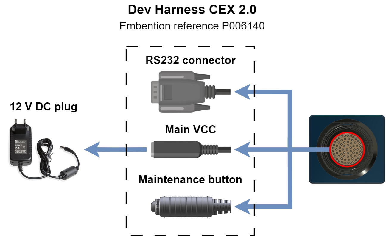
For further information on the Dev Harness CEX 2.0 connectors, refer to the Dev Harness CEX 2.0 - Hardware Installation section of the present manual.
Warnings
- Disassembling, improper installations or bad connections may invalidate the warranty. Please contact Technical Support if you suspect a faulty or defective component.
- CEX will always produce heat as a by-product of its operation. Keep in mind an adequate heat dissipation on installation.
- RS-485 has internal termination resistor.
- I2C is equiped with 4.7K internal pull-ups.
- Pins 1 and 2 (see Pinout) can be powered by 2 power supplies with different voltages as they are independent. Although they do have to share the Ground.
- Not to exceed the values of any of the Electrical specification.
- CEX does not integrate a termination resistance in order to allow the connection of multiple CEX or other CAN Bus devices to the same line. To do this, visit section CAN assembly of this manual.
Requirements
- Veronte Link (v6.8.X or higher).
- CEX firmware version/CEX PDI Builder (v6.8.X or higher).
- Veronte Autopilot firmware (v6.4.X or higher).
- Veronte Updater (v6.8.X or higher).
© 2026 Embention. All rights reserved.