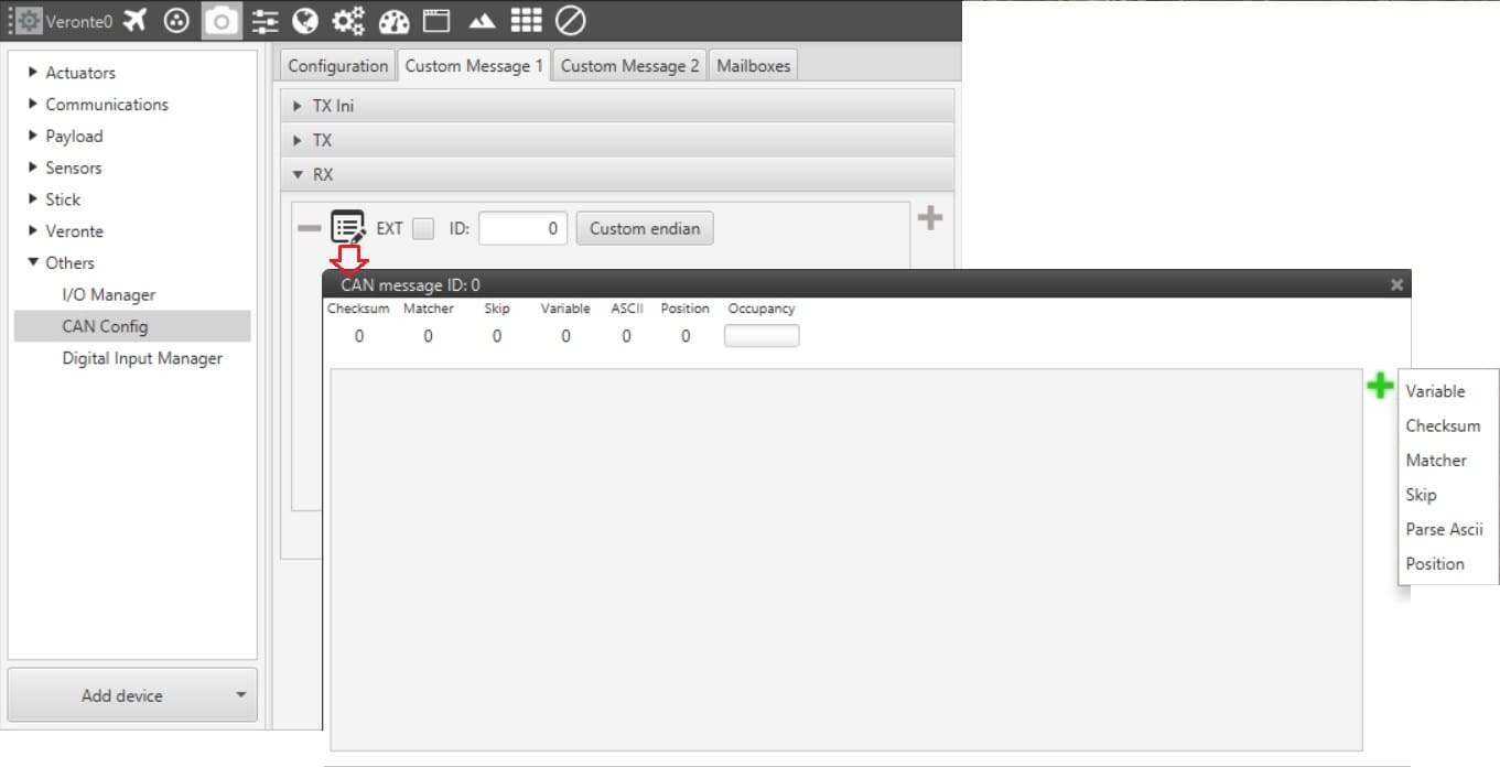
CAN Messages
When using and configuring CAN messages either TX (transmitted) or RX (received), the following types of message are available.
Telemetry Panel
Variable
Used to store certain bits in a system variable (RX) or to send a certain variable through the CAN bus (TX).
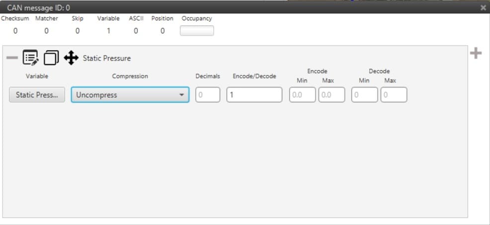
Variable Configuration Menu
Type of Compression. The first step is to configure which kind of compression will be used for this variable.
Uncompressed. The variable is taken in its full length, with no value modification. If it is a 32bits variable, it will take all 32bits from the CAN message directly.
Compress. The three subcategories of compressed Variable allow the user to input a digit, which is explained in the following lines:
Compress (Decimals). Sets the number of decimals to use i.e, if the AGL has a value of 500.43453, it will be compressed to 500.43.
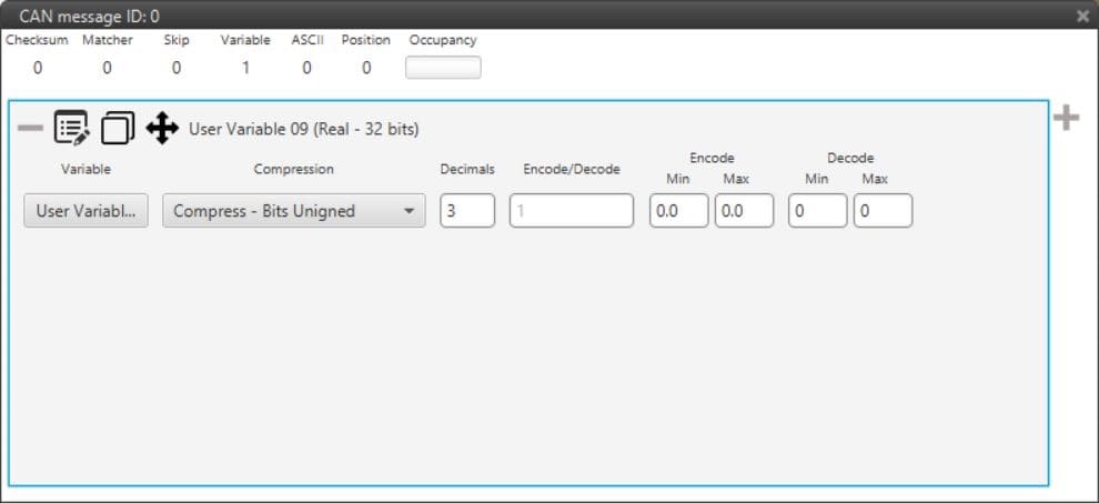
Compress (Bits signed). Sets the number of bits, and these can be signed i.e, negative values are admitted. It is necessary that the user configures Encode/Decode options.
Compress (Bits unsigned). Sets the number of bits which will not accept negative values. It is necessary that the user configures Encode/Decode options.
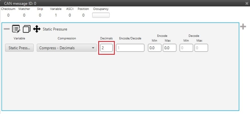
Compress Decimal Selection
Encode/Decode. These values are used to apply a scaling factor after the transformation from binary to decimal value.
When reading data from a CAN bus it is common to have information about the message layout. In that case, let’s consider that the first 3 bits correspond to a certain variable. If that variable is always positive, unsigned has to be selected, if it could be positive or negative select signed. The fields Encode/Decode are used to make the transformation from binary to decimal, corresponding Encode to the decimal value and Decode to the binary one. Considering the example shown in the following figure, the binary number is divided by 10 to make the transformation to decimal (and decimal multiplied by 10 to go to binary), so the variable represented here will go from 0 to 0.7 (as 3 unsigned bits can represent numbers from 0 to 7).
Variable Identification Example
Checksum
Sometimes, control codes are needed for preventing random errors in transmission, where a bits frame is operated and the result is sent to the receiver to check it. To do so the CheckSum option is used.
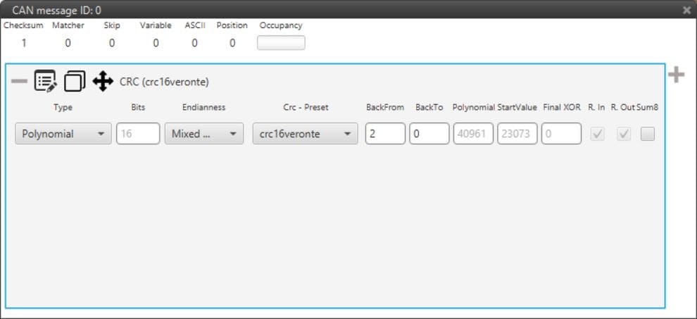
CheckSum
Back From: Indicates that the CRC will be computed from the indicated byte (inclusive).
Back To: Indicates that the CRC will be computed to the indicated byte (exclusive).
Note
Byte 0 it is referred to the first byte of the Checksum block. i.e for a message with 6 bytes where 2 bytes are the CRC. Back from = 4 and Back To = 0
Endianness: Indicates how the bytes that it contains are read:
Big endian: Set the value from left to right
Little endian: Set the value from right to left
Mixed endian: For some special devices.
Type: User can choose the type of CRC that will be applied.
CRC type.
Polynomial. Select from a list of predefined Embention Veronte CRC. Last option is Custom, where fields as nº Bits, Polynomial, Start Value, Final Xor, Reflect In and Out can be defined. Check Polynomial CRC online for more information.
Module. Applies Module CRC.
Mavlink. EMbention has implemented the Mavlink checksum, used only for Mavlink protocol communications.
Sum 8. The Sum 8 checksum is the 8 bit modulo 256 checksum. It consists of adding all bytes to take only the less significant bits whenever the sum exceeds 8 bits (255). The algorithm will be:
SUM = Sum on all bytes
CHECKSUM = MOD(SUM,256)
Matcher
This option is used to send a constant value through the CAN bus in TX or wait for a particular value in RX.
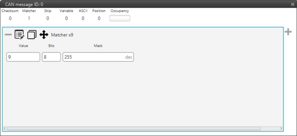
Matcher
Nº Bits: number of bits in which the matcher is performed.
Value: sent/received value for the above nº of bits.
Mask: it is automatically set when the nº of bits is assigned.
For example, a matcher of 8 bits with a value of 9 will be reading/sending: 0000 1001 .
Skip
This option is used to discard a certain number of bits from the message (the maximum number of bits that can be skipped with a single “Skip” are 32). This tool can be used when there are variables incoming that are from no interest for the user, not loading unnecessary information into the system.
Parse ASCII
Parsing ASCII is used when the protocol required is of this kind. Only for RX. The variable set at the top is where the ASCII will be saved.
ASCII protocol is used for transforming a character array into decimal values. For such task, the user needs to define the number of characters in the integer and the decimal parts, as well as defining which is the division character. See how to introduce all this information in the picture below.
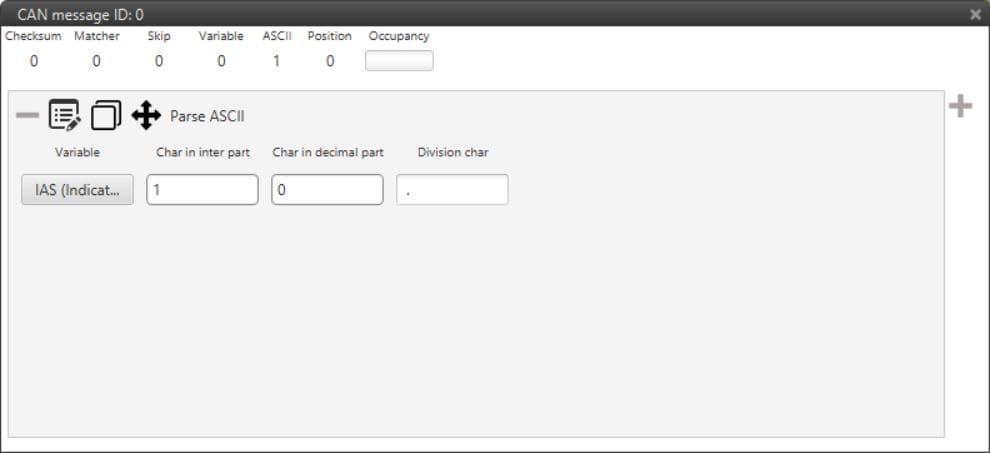
Parse ASCII Menu
Position
Position is used to input/output a data set with a particular format. When created, the user can only choose from Moving Object variables.
The window display below is the configurable menu, where it can be chosen between degrees and radians as units. The information stored is the WGS84 coordinates in the following order: Latitude, Longitude and Height. All of them are stored with double precision.
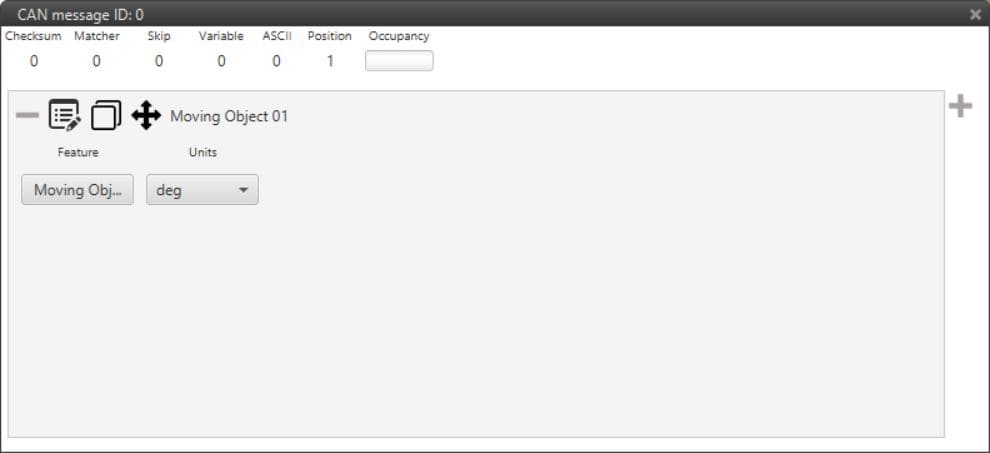
Position Menu