GNSS Compass
GNSS Compass menu allows the user to access to the RTK - Compass Wizard (an interface which helps the user configuring everything related to RTK - GNSS Compass) and some other parameters which could be changed afterwards or if the user has knowledge enough.
GNSS Compass - Configuration Menu
By clicking on RTK - Compass Wizard button, the user will access the configuration menu where three options will be displayed.
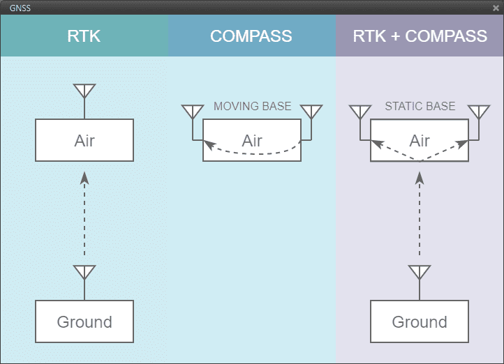
GNSS Compass - RTK & Compass Wizard
RTK. Stands for Real Time Kinematics and it is a satellite navigation technique used to enhance the precision of position data derived from satellite-based positioning systems. It requires from 2 GNSS receivers placed in different autopilots to work.
Compass. The GNSS compass provides accurate dual antenna GNSS based heading that is not subject to magnetic interference. It requires from 2 GNSS receivers placed in the same autopilot to work.
RTK + Compass. A hybrid combination where both tool are employed at the same time in a system where the AIR unit must have 2 GNSS receivers and the GND, at least, must have 1.
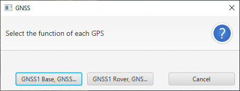
When accessing the GNSS Compass feature, the user will be asked which configuration is preferred in accordance to the function of each receiver:
GNSS 1 Base and GNSS 2 Rover.
GNSS 1 Rover and GNSS 2 Base.
GNSS Compass - Compass Base/Rover
Warning
It’s possible that Compass options are blocked in Wizard if the position of GNSS antennas is not defined. To avoid this problem, change the distance to the center of mass in aircraft body frame in Devices/Sensors/GNSS.
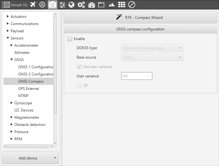
These same parameters can be manually changed afterwars in GNSS Compass Configuration. After using the wizard, the Enable check will be marked. The options enabled this way are:
DGNSS Type. Where the option available are “Rover with moving base” and “Rover with rover (static base)”. The first option references to GNSS Compass, while the second is used in RTK with Compass. Consider the parameter established will be the one coming from the Wizard configuration.
Base source. Where option are GPS 1 or 2.
To configure the rest of parameters in Compass mode, user has to modify the GNSS configuration and message rate. First, set the MEAS rate to 0.5. Then configure the protocols. Rtcm3 is enabled in mask in for the GNSS configured as rover, and in the mask out for the GNSS base. The message rates are different in each GNSS. The essential messages are shown below:
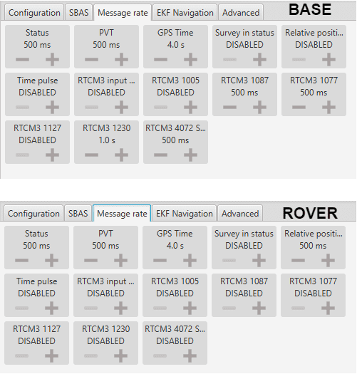
GNSS Compass - Compass Message Rate
In the I/O Manager menu (Devices - Others), base GNSS (producer) sends RTCM information to rover GNSS (consumer).

GNSS Compass - Compass I/O Manager
The RTK - Compass Wizard does also appear as a red notification on the bottom right side of Veronte Pipe.
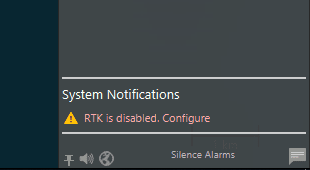
GNSS Compass - Configuration Notification
By clicking on it, the Wizard will ask the user which AP is the AIR unit and which one is the GND (in case RTK functionality is expected) and afterwards, the GNSS Compass wizard will be displayed and use in the same way.
RTK Configuration
Apart from the wizard option, it is possible to configure RTK following the next guide. First, it is needed to configure Ground Station setup. Ground station has two GNSS ports. User can choose one of them to carry out the RTK technique (Using Wizard tool the first GNSS is chosen by default). The main parameters are shown in the picture below.

GNSS Compass - RTK configuration (Ground Unit)
Meas Rate: measurement rate. The optimal is fixed in 0.5.
Protocols: rtcm3 has to be enabled in Mask out.
Survey in: to configure the minimum ‘Survey In’ accuracy and for how long the accuracy needs to be held within this range in order to enable the RTK feature.
Then, the following messages need to be configured in the ‘Message Rate’ tab. They are properly selected in the next picture.

GNSS Compass - RTK Message Rate (Ground Unit)
Finally, go to the I/O Manager, and add a message by a tunnel with RTCM information. This will be sent to AIR UNIT to correct their GNSS measurements and improve their accuracy.
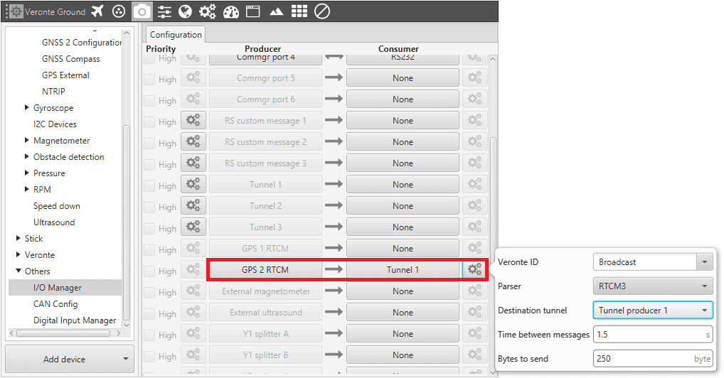
GNSS Compass - RTK I/O Manager (Ground Unit)
Now, it’s time to configure the AIR Unit. Meas Rate to 0.5, and rtcm3 enabled in Mask in (Protocols). The message rate has to be configured as follows:

GNSS Compass - RTK Message Rate (Air Unit)
The last step consists of configuring I/O Manager to receive RTCM message sent by the tunnel (Ground unit). If user wants to receive position corrections in both GNSS devices the tunnel has to be splitted in 2 channel (1). Then, user has to link these splitted channels to GPS RTCM (2).
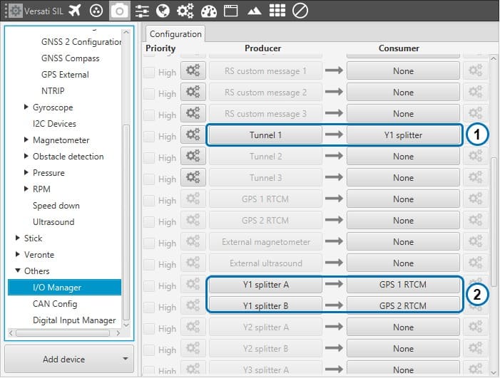
GNSS Compass - RTK I/O Manager (Air Unit)