Envelope
Menu to configure the flight envelope of the aircraft. Here the limits that will not be exceeded during the operation are set.
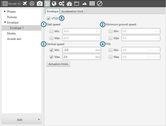
Envelope
Stall speed: limit for the indicated airspeed (IAS). The value indicated here has effect over the “Cruise” guidance, but is overrided if there is a Hold command on the IAS, so the user must be careful with the velocity commands. Besides, there is an option name as stall speed max that refers to the limit the uav shouldn’t exceed.
Ground speed: minimum and maximum ground speed of the platform. In case of strong wind, these parameters set the minimum GS that the aircraft can reach, for lower values than this one the thrust will be automatically increased to gain speed and avoid a point where the platform is stopped in the air.
Vertical Speed: similar to the previous limit. It sets the minimum and maximun value for the vertical speed of the platform.
FPA: maximum and minimum values for the flight path angle (angle of climb or descent).
VTOL: If this option is enabled, when the vehicle reaches the last waypoint of its route (and it is an open path), a hover is done instead of a loiter point.
It’s possible to insert multiple envelopes (useful for hybrid configurations). The change between envelopes can be performed using Automations.
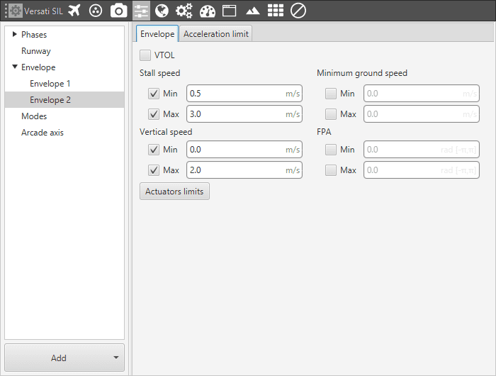
Multiple envelope configuration
In the second tab there are more options to fix the limits (rising and falling) of acceleration and jerk in SI units.
Acceleration limits are applied in any phase with position guidance. They modify the desired velocity. The algorithm compares the current desired velocity with thatstored in previous step. There are six values to define. The configurable options in this menu are:
Enable/Disable the acceleration limit.
Type : User can choose between cartesian frame o spherical frame.
Rising limit : The limit for acceleration. If desired velocity has the same sign as in the previous step, and it’s is lower (in absolute value) this limit is applied. For example, if a multicopter is fliying in negative X direction, and it has to increase desired velocity in same direction this limit will be applied.
Falling limit : The limit for deceleration. In the case rising limit is not used.
Axes : In cartesian mode they reference body frame (Longitudinal X, lateral Y, and Bottom Z). In spherical type, the algorithm internally applies limits in module, inclination and azimuth to maintain the limits set by the user in body frame (body frame limits will be turn into spherical limits). The user also can selected directly angular rates option (6) which allows him set limits in Heading rate and Flight Paht angles rates.
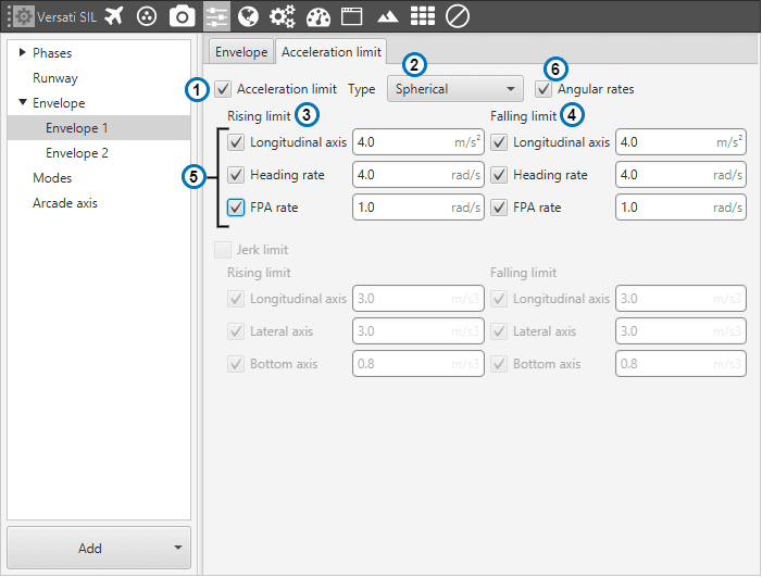
Acceleration limit (Spherical frame)
The second derivative of velocity (jerk) imposes another limit in acceleration. It modifies the behaviour of the vehicle. Depending on values, it’s possible to get more smoothness during guidance. Algorithm ensures that when desired velocity is reached the acceleration value is near 0. As acceleration limits, user can set 6 values (3 for rising limit and 3 for failing limit).
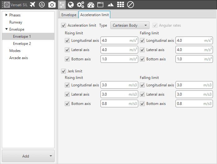
Acceleration limit (Cartesian frame)
The effects of these limitations are explained below.
First, the acceleration limits are disabled. The stick that controls Thrust is moved and desired velocity change according to this stick command. In Desired velocity chart we can see this effect and in bottom acceleration chart is shown how acceleration is not limited (hight values reached).
Only velocity limit (Thrust)
Now, a limit in acceleration bottom axis is set to 0.1. Now the desired speed grows with a lower slope due to the imposed limitation. Also in the acceleration bottom chart we can see how the value oscillates within the imposed limit.

Acceleration limit (Thrust)
To compare acceleration and jerk, roll axis is chosen. In the first gif below only the first limit is applied.

Acceleration limit (Cartesian frame)
When the jerk limit is also enabled we can see how acceleration (in Y Body axis) does not show peaks, and changes in desired velocity are smoother.

Acceleration limit (Cartesian frame)