GPIO/PWM
Output pins produce PWM or GPIO signals that are used to move the different servos and actuators of the platform.
GPIO
A GPIO (General Purpose Input/Output) is a generic pin that can be configured as an input or output pin. When this option is configured as an output pin, the value sent will be different from the one sent if it was a PWM. GPIO pins admit up to 4 different states: ON (a continuous signal of value 1, made by 3.3V), OFF (a continuous signal of value 0, made by Ground), PULSE ON (a single pulse of value 1, with a width specified in seconds) and PULSE OFF (a single pulse of value 0, with a width specified in seconds). The configuration of the pin output value is done with an action Output in Automations.
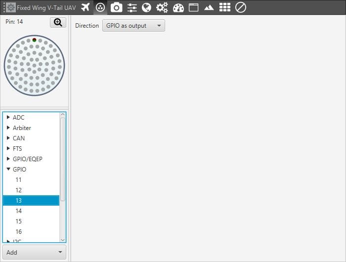
GPIO Menu
PWM
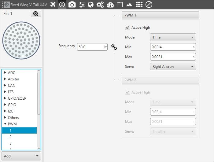
PWM Menu
The acronym PWM corresponds to Pulse Width Modulation. Veronte sends a pulse with a certain width that is received by the servo/actuator, and according to the width of such pulse, it changes its behaviour. A wide pulse will correspond to a big movement and a narrow one to a small movement.
The Min and Max parameters are the pulse width values that will make the servo/actuator go to its lowest and highest position. As an example let’s consider the servo of an aircraft elevator, a pulse sent by Veronte of 0.9 ms will correspond with the lowest point of the servo range (-30 degrees for example). On the other hand, a pulse of 2.1 ms will make the servo go to its top position (for example 30 degrees).
The option duty cycle (select mode/duty cycle) is a different way of indicating the pulse width. Now the value indicated is a percentage which corresponds to the relation between the pulse width over the total period of the sent signal. So a 100% duty cycle will correspond to a signal with a constant value of 1, while a 0% duty cycle implies a constant signal with value 0. Between this two extremes, the pulse width can vary as in the examples shown in the following figure.
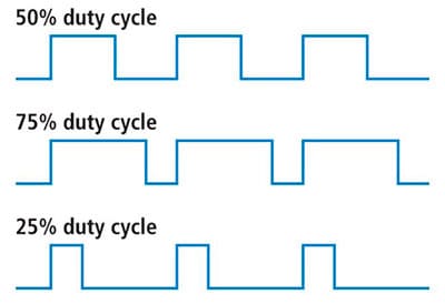
Duty Cycle
The option Servo is used to select which servo of the platform will be wired to that pin of Veronte connector, so the signal sent through that pin will go to it. The name of the “Actuator Output \(S\)” can be changed to other more identifiable according to the real actuator such as right or left aileron, see section System Variables.
The option Frequency determines the period of the pulses sent by the autopilot. The PWM is built in pairs inside the autopilot, and that is why the frequency is indicated in pairs, i.e when the frequency of PWM 1 is changed, the one of PWM 2 also changes. The following table shows the PMW pairs as configured in Veronte autopilot.
PWM Pairs |
|
|---|---|
PWM 1 |
PWM 2 |
PWM 3 |
PWM 4 |
PWM 5 |
PWM 6 |
PWM 7 |
PWM 8 |
PWM 9 |
PWM 10 |
PWM 11 |
PWM 12 |
PWM 13 |
PWM 14 |
PWM 15 |
PWM 16 |
To sum up, a PWM is a signal which consists of a series of pulses having a width determined by a percentage over a range specified by the parameters Min and Max. On the other hand, the GPIO is a signal with a constant value (1,0) or with a single pulse (1,0).
Add
Veronte admits up to 16 I/O PWM/GPIO signals. To configure a pin as PWM or GPIO, click on Add and select PWM or GPIO. The following windows will be displayed according to the option selected.
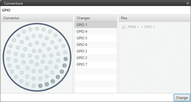
GPIO Selection
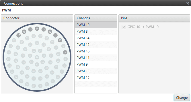
PWM Selection
As can be seen, pins are interchangeable. Once selected the desired pin, click on Change.