Altimeters
The integration between Veronte and a lidar is performed using a variety of interfaces depending on the lidar device. The most common interfaces are I2C or analog although serial or CAN bus can also be used if the lidar is compatible.
Reading altimeter measurement
ADC lidar
An ADC lidar changes the voltage according to the distance measured and therefore the connection to Veronte is performed using the ADC pins(see section Electrical).
Warning
4x Redundant Veronte autopilot has different ADC pins.
Once connected the value can be monitored in Veronte Pipe by using the variables ADC1 to ADC5. For pin ANALOG_1 the correspondent ADC variable in Veronte Pipe is ADC1.
Go to Programs.
Configure the following operation:
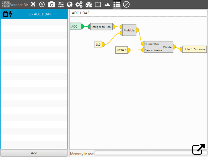
Lidar operation
After implementing the operation the variable Lidar 1 Distance will represent the distance measured by the lidar.
Note
4x Redundat Veronte can read up to 36 V for each ADC thus 3 must be chanted to 36 if it is the case.
I2C lidar
I2C lidars are configured slightly different. Connect the lidar following the pinout provided by the manufacturer and connect it to the I2C bus of Veronte by following the section Electrical. In this case it is not needed to transform the readings from the lidar, the readings will be directly reported in the selected lidar distance variable..
Go to Devices/Sensors/I2C devices.
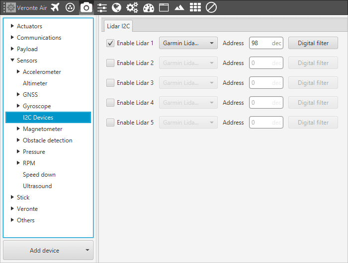
I2C Lidar
Note
I2C address will be different for different devices make sure to define it properly by checking the manufacturer documentation.
CAN Radar
Radar altimeters are common devices for aircrafts. The following pictures correspond to the integration of the Smartmicro Radar. To get more information of the Smartmicro Radar - Altimeter datasheet you can go to:
This settings will allow Veronte to read from CAN A readings from the radar altimeter. In particular AGL and vertical speed. In the datasheet the user can access to the complete protocol of the device.
Go to Connections/CAN/A in the setup toolbar and configure the baudrate.
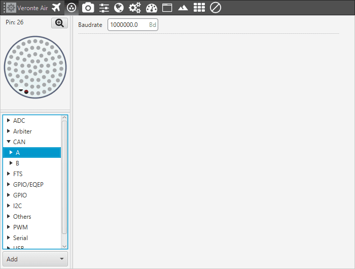
Baudrate configuration
Once the baudrate is set, go to Devices/Others/CAN Config/Configuration.
Set one input filter to read from CAN A in custom message 1, in this case Input Filter 3. On the next steps CAN custom message 1 will be configured.
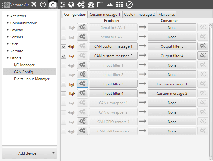
CAN routing configuration
After specifying that custom message 1 will receive the data from CAN A, go to Devices/Others/CAN Config/ Mail Boxes.
Set the mailboxes for the CAN message id: 1872
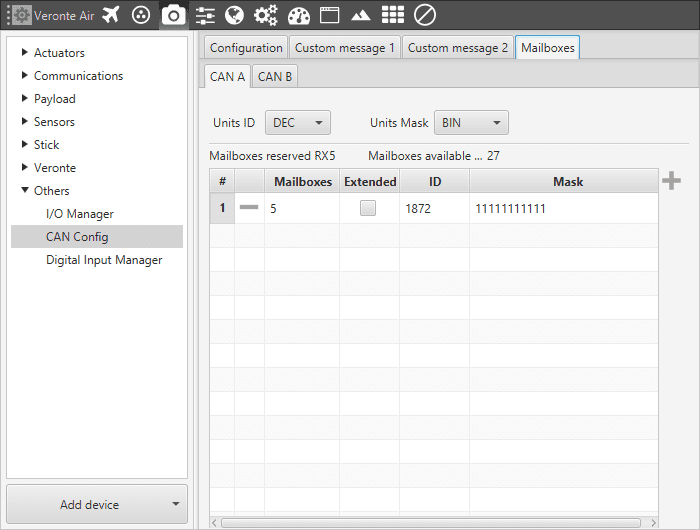
Mail boxes setting
Move to the tab Custom message 1 and add new message under RX with the ID 1872.
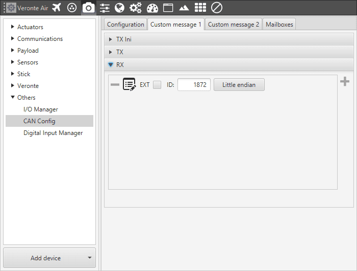
Rx message definition: Id and endianess
Define the content of the incoming message:
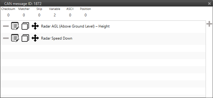
Rx message definition: message content
For more details about CAN messages configuration see Custom Messages.
Note
CAN ID messages and messages content will change for different Radar altimeters. Check the documentation of your device for further details.
Using altimeter readings
Once the information provided by a lidar sensor is saved in a system variable as Lidar Distance by means of an ADC reading, I2C, serial or CAN. The user has to set how this data will be considered. Common usages are: triggering an action based on a predefined event or considering the lidar data as external sensor which will be considered as an input to the EKF.
Automation:
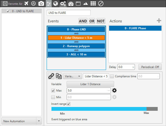
Lidar Automation example
This automation will be triggering a change of phase, flare phase, when the aircraft is landing and at 5 m AGL.
External sensor:
Further information about this menu can be found in altimeter section.
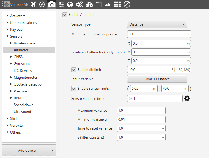
Altimeter configuration