Autopilot Radio Pairing
This section includes the information of how to pair the GND and AIR autopilots. Also, the configuration of the parameters of the radio module inside each unit will be covered. The steps described in here must be first performed on the GND unit, and then on the AIR one.
First display the Setup Toolbar: click on ![]() and then click on Setup. This toolbar allows the user to modify the main features of the autopilot.
and then click on Setup. This toolbar allows the user to modify the main features of the autopilot.

Setup Toolbar
Now click on ![]() Radio. The following menu pops up:
Radio. The following menu pops up:
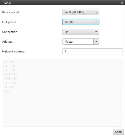
Radio Configuration Menu
All these parameters have to be set accordingly to the radio module installed in the Veronte autopilot. Contact Embention if you need the details of your specific radio module.
Radio Module: each autopilot has only one of the following radio modules P400/900, P900 and P2400. Select here the radio module installed.
Output power: set the desired power output.
Connection: Point to Point or Point Multi Point. That will depend on your mission and on the number of autopilots required in the same LOS network.
Address: Master or Slave. Select the role for each autopilot by selectig master or slave. By default the AIR unit is defined as slave and ground units as master.
Network address: the network address is a number that must be equal between autopilots using the same network. First the master´s address should be filled in so when the slave’s is set to the same value, the GND autopilot will find the AIR autopilot and bind a connection with it.
By pressing Send the user sets all parameters .