Hardware Installation
Danger
The system slowly discharges the voltage on the input terminals when the battery is disconnected. Capacitors may remain charged unless enough time has elapsed.
Note
When working voltage is higher than 60 V, use of insulating gloves are mandatory for installation and the system must have a chassis fault detection system.
Mechanical Assembly
To fix the MC110 to an aircraft frame, take a look to the dimensions and screws positions. Screw holes must be deeper than 6 mm with M6.
Vibration Isolation
There might be situations where external isolation components might be needed.
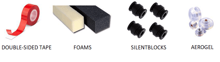
Veronte MC110 can be mounted in different ways in order to reject the airframe vibration. The simplest way CAN be achieved by just using double-sided tape on the bottom side of MC110. Other ways may use some external structure which could be rigidly attached to the airframe and softly attached to Veronte (e.g. foam, silent blocks, aerogel, etc).
The user should take into account that wiring should be loose enough so vibrations may not be transmitted to MC110.
In cases where mechanical isolation is not viable, it is possible to use soft engine mounts. It is also recommended when there are other sensible payloads like video cameras or for high vibration engines.
ESC-Motor Wiring
Warning
The polarity connection of the input must be respected, otherwise a short circuit may occur.
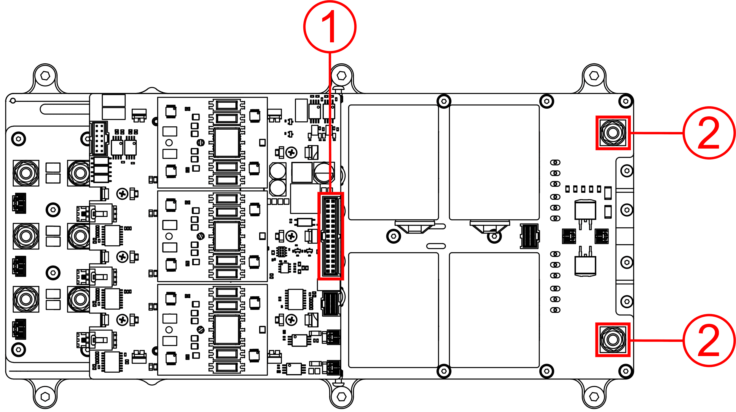
The Sensor Connector is easily accesible, but to access the User Connector it is necessary to unscrew the cover from both sides and pull it up.
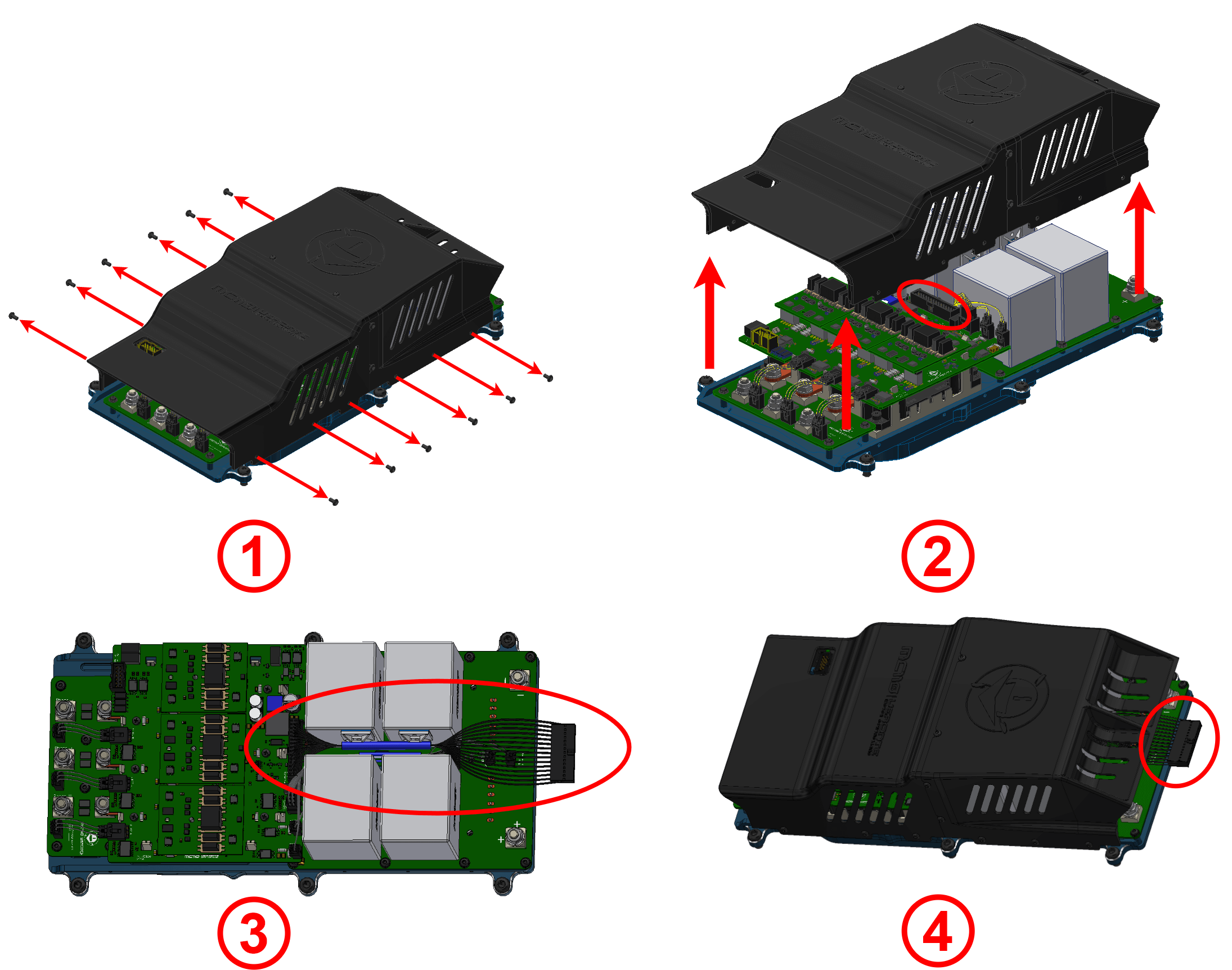
How to access the user connector
The polarity and connections are indicated in the following image and table.
Nº |
Name |
Description |
|---|---|---|
1 |
HV negative |
Input power from DC current 100 to 800 V DC |
2 |
HV positive |
|
3 |
Phase U |
Output power to motor |
4 |
Phase V |
|
5 |
Phase W |
|
6 |
Sensor connector |
Encoders and sensor temperature signals |
7 |
User connector |
Communications, telemetry and control signals |
The section of the cables must be dimensioned according to the maximum power that will be used
Battery cables between MC and battery should be as short as possible. If the distance between battery and motor is long, please extend phase cables in order to shorten battery cables.
Tip
Connection of the phases can be done freely, however, it will affect the direction of rotation of the motor. Hence, if the motor is spinning in the opposite direction, switch any 2 phases around.
Pinouts
User Connector
The user connector pinout is shown in the following figure and table:
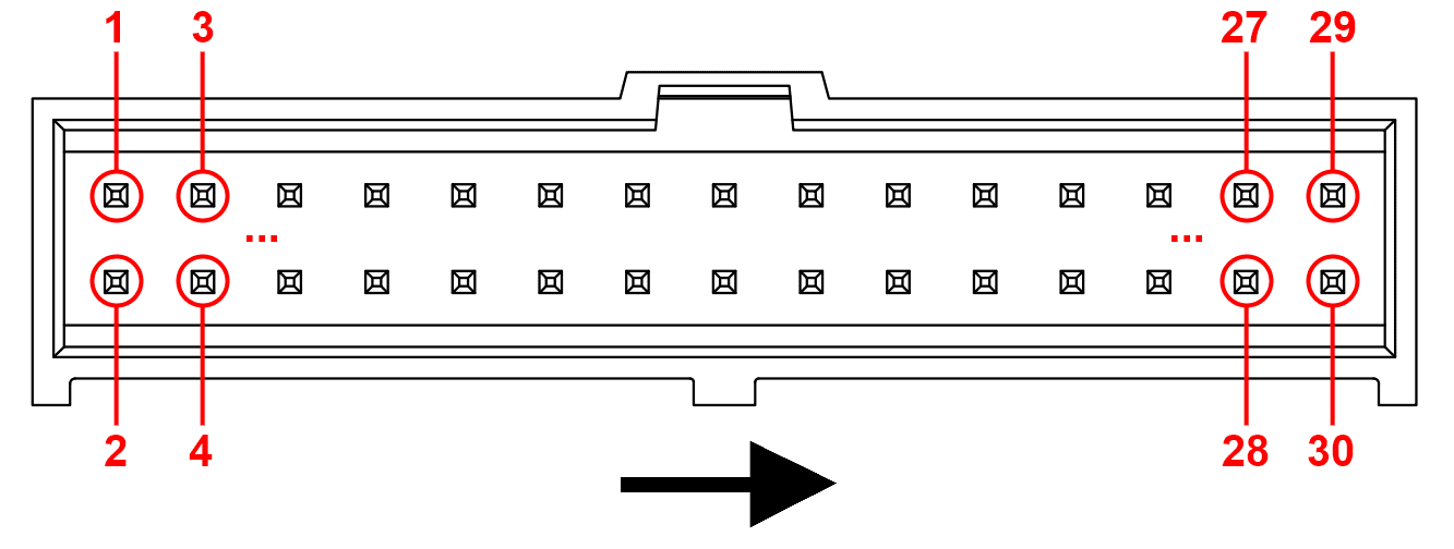
Pin numbers of user connector
User connector |
|||||
|---|---|---|---|---|---|
Nº |
Name |
Description |
Nº |
Name |
Description |
1 |
SYNC_ID_IN |
Input Signal for Sync Identification * |
2 |
SYNC_ID_OUT |
Output Signal for Sync Identification * |
3 |
GND |
Ground |
4 |
GND |
Ground |
5 |
SYNC_OUT * |
Output PWM to synchronize multiple MC110 units |
6 |
SYNC_IN * |
Input PWM to synchronize multiple MC110 units |
7 |
GND |
Ground |
8 |
RS232_TX |
RS-232 transmitter |
9 |
OUT_485_P |
RS-485 output positive |
10 |
RS232_RX |
RS-232 receiver |
11 |
OUT_485_N |
RS-485 output negative |
12 |
FAN_PWM |
Digital PWM output for fan control |
13 |
IN_485_N |
RS-485 input negative |
14 |
HEARTBEAT |
Error diagnosis signal |
15 |
IN_485_P |
RS-485 input positive |
16 |
GND_485 |
Ground for RS-485 |
17 |
OPTO_PWM |
Digital Input for motor speed. Optocupled inside MC110 |
18 |
OPTO_RTN |
Return of pin 17 |
19 |
CANFD_N |
CAN FD negative pin |
20 |
CANFD_P |
CAN FD positive pin |
21 |
22 |
||||
23 |
GND_CAN ** |
Isolated ground for CAN |
24 |
GND_CAN ** |
Isolated ground for CAN |
25 |
CANB_N |
CAN B negative pin |
26 |
CANB_P |
CAN B positive pin |
27 |
28 |
||||
29 |
GND |
Ground |
30 |
VCC |
Digital power supply 8 - 36 V |
* :Synchronization between MC110s optimizes battery management.
** :Ground for CAN is not necessary, but it can be used in case of having issues with CAN signals.
Sensor Connector
The sensors connector pinout is shown in the following figure and table:
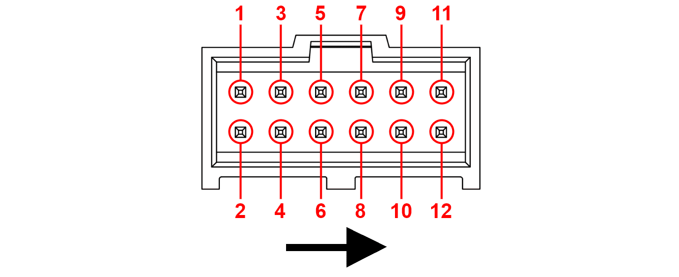
Pin numbers of sensor connector
Sensor connector |
|||||
|---|---|---|---|---|---|
Nº |
Name |
Description |
Nº |
Name |
Description |
1 |
ENC_SIN |
Sine input from encoder |
2 |
ENC_COS |
Cosine input from encoder |
3 |
GND_ISO |
Isolated ground |
4 |
5_V_HALL |
Isolated 5 V |
5 |
ENC_A * |
Encoder A |
6 |
||
7 |
ENC_B * |
Encoder B |
8 |
ENC_Z * |
Encoder Z |
9 |
GND_ISO |
Isolated ground |
10 |
ISO_TEMP |
External temperature sensor measurement |
11 |
12 |
1_V |
Power supply for external temperature sensor (1 V) |
||
* These inputs are digital, incremental and optocupled inside MC110.
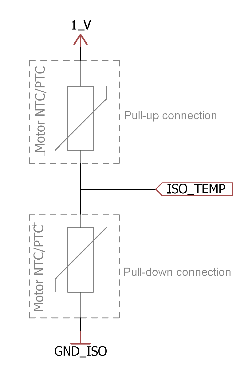
If the temperature sensor is connected as a pull-up resistor, pin 1_V (12) will be the voltage reference.
If the temperature sensor is connected as a pull-down resistor, pin GND_ISO (3, 9 or 11) will be the voltage reference.
How to Turn On and Off
MC110 has two electric circuits: control and power. To turn on the voltage supply (with devices such as switches, relays or MOSFETs), it is mandatory to do it with the following order: first of all the control group, and then the power group.
The control group is in the user cable. The power circuit is in the negative and positive cables. Then the enabling order is summarized in the following figure:
Turn on order
To turn off the MC110, the disabling order is reversed: first power circuit (input negative and positive), then the control circuit (user cable).
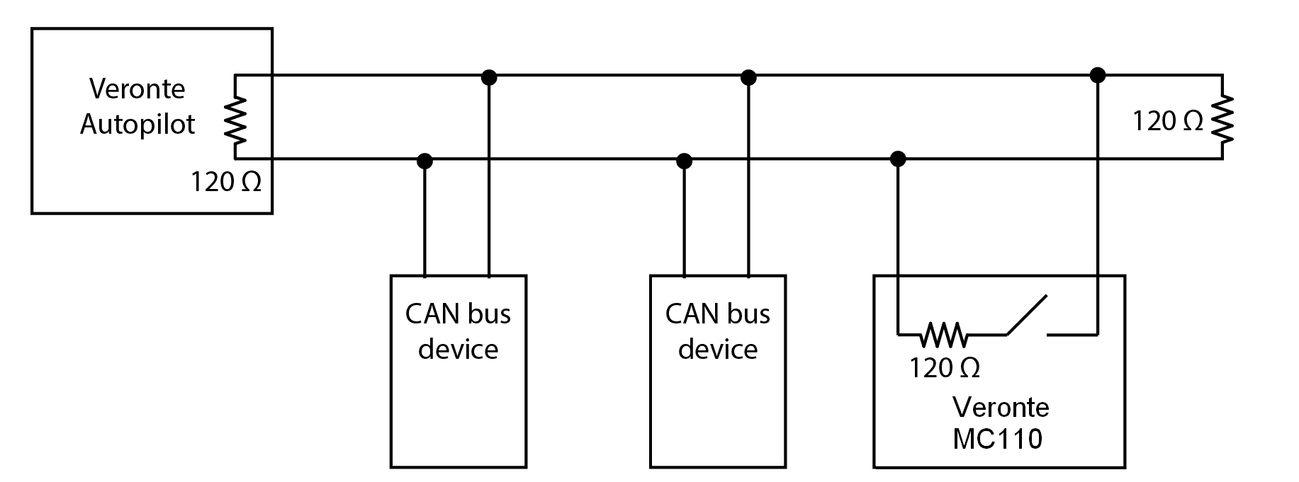
Electrical Diagram of CAN Bus
Like any other CAN device, Veronte MC110 requires a termination resistor to allow the connection of multiple MC110s or other CAN bus devices to the same line.
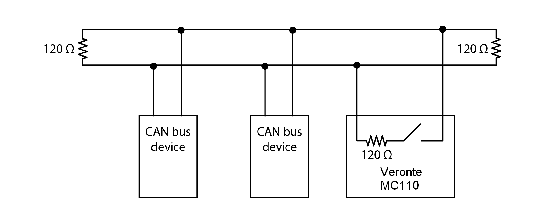
Typical CAN diagram
Considering Veronte Autopilot includes one entrance resistor of 120 Ω, a second resistor needs to be placed at the end of the line (120 Ω). This resistor may be placed on the cable or on another PCB.
CAN diagram with Veronte Autopilot
MC110 has an internal resistor of 120 Ω, which can be activated by software. Then, another way to connect multiple CAN bus devices lies in connecting a MC110 to the end of line, then activating its internal CAN resistor. Read Configuration -> Mailboxes section of MC110 PDI Builder manual to enable or disable the resistor.
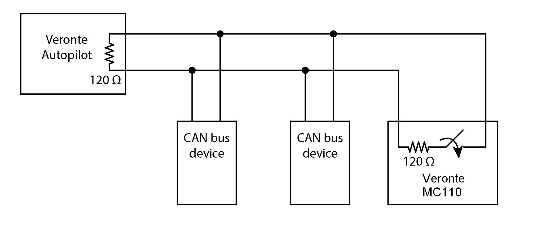
Diagram with CAN resistor activated
Cooling Circuit Design
Warning
Do not place the MC110 or its cooling circuit close to another heat source, since it would be counterproductive for the refrigeration, compromising its performance and safety.
Note
The following explanations assume there are not phase changes on the coolant, since it is not necessary to use a refrigeration system with phase changes.
MC110 is able to control motors up to 110 kW due to liquid refrigeration systems. The motor controller only includes the cold plate, requiring the rest of the refrigeration system (pump, pipes, radiator, expansion tank and coolant).
This manual explains two ways to design a cooling circuit, click on the desired one:
Simplified. For one MC110 with a specific type of cooling circuit.
Advanced. Generic indications to design a completely custom application.