Software Applications
Veronte Link
Veronte Link establishes communication between a computer and any Veronte product by creating a VCP bridge.
It allows multiple control stations and autopilots to be interconnected, operating simultaneously.
Veronte Link also includes a post-flight viewer to reproduce all recorded data from previous flights and generate plots and reports.
For more information, visit the Veronte Link user manual.
1x PDI Builder
1x PDI Builder is the main configuration tool to adapt a Veronte Autopilot 1x to a specific vehicle, including user-defined communication protocols.
1x PDI Builder includes:
- Telemetry: Real-time onboard UAV metrics, such as sensors, actuators, and control states.
- Configuration: Edit vehicle settings, such as servo trim, interface/port management, and modes.
- Automations: Actions that are automatically executed when a set of configured conditions is met.
- Block Programs: Veronte Autopilot 1x can be programmed with a user-friendly programming language.
For more information, visit the 1x PDI Builder user manual.
Veronte Ops
Veronte Ops is the application used to operate and monitor the vehicle during missions.
To know more, read the Veronte Ops user manual.
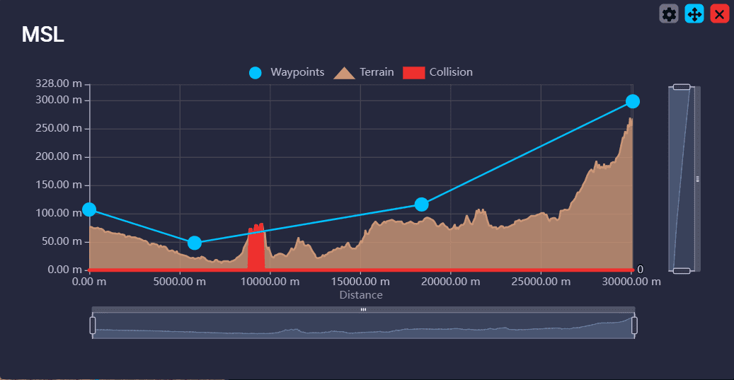
Veronte Terrain Provider estimates and displays the terrain height and the aircraft height.
When working in conjunction with the Veronte Ops application, it helps to avoid collisions.
For more information about Veronte Terrain Provider, read the Veronte Terrain Provider - Additional apps section of the Veronte Ops user manual.
Veronte HIL
Veronte HIL (Hardware In the Loop) is a simulation package for autopilot integration, development, and operator training.
This software allows extensive operation of the flight system in a simulated environment before executing real flight operations.
Its role is to perform HIL simulations with the real autopilot hardware, allowing the use of simulation applications like X-Plane, Microsoft Flight Simulator, or Simulink.
For more information, visit the Veronte HIL user manual.
Veronte Updater
Veronte Updater updates all Embention products.
For more information, visit the Veronte Updater user manual.
1x PDI Calibration
1x PDI Calibration sets up calibration parameters for 1x autopilots.
It allows the user to calibrate sensors, servos, and configure the radio module.
For more information, visit the 1x PDI Calibration user manual.
Veronte FDR
Veronte FDR manages autopilot files, allowing users to download registers generated by the autopilot and convert them to CSV files.
Three types of registers can be downloaded: Onboard log, Fast log, and User log.
For more information, visit the Veronte FDR user manual.
Veronte VSA
Veronte VSA works using a flight simulator to represent worldwide geographical scenarios: lands, seas, mountains, cities, airports, airfields, heliports...
Additionally, an internet connection is not necessary, allowing operation from any location without delays in scenario loading.
Veronte VSA displays a 3D view of the piloted aircraft and can be used as a 3D PFD (Primary Flight Display) when using the first-person camera view.
This system allows custom aircraft models to be displayed in the virtual environment. The Planemaker tool is available for creating custom models, enabling operators to visualize aircraft models in the interface.
For more information, visit the Veronte VSA user manual.
1x PDI Tuning
1x PDI Tuning allows managing the control laws of the Autopilot 1x during operation.
Users can adjust each P (Proportional), I (Integral), and D (Derivative) gain and select the PID type (Standard or Parallel).
For more information, visit the 1x PDI Tuning user manual.
Nomenclature
This section defines the nomenclature convention employed by the software applications.
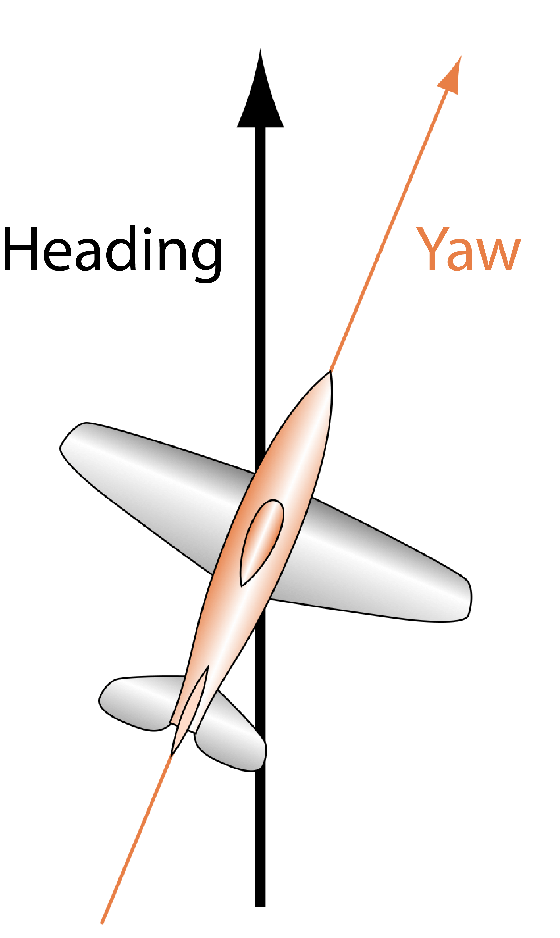
Reference Directions
- Yaw is the direction where the aircraft is pointing. It does not depend on the movement, as Yaw is aligned with the longitudinal axis of the aircraft.
- Heading is the movement direction projected to the ground. Heading does not depend on wind or Yaw direction; it only depends on the ground and the aircraft's movement.
Important
Both Yaw and Heading angles are measured concerning the True North, not the Magnetic North.
Axes
All signs are defined according to the international aeronautical axes convention:
Any deflection that generates positive rotational forces relative to the aircraft's aerodynamic center is considered positive, except for the "y" axis (elevator), where downward movement is considered negative.
For example, when the elevator moves down, it generates a positive pitch, so the elevator is considered positive in the lower position.
Main Actuator Rules:
| Actuator | Positive | Negative |
|---|---|---|
| Elevator | Down | Up |
| Rudder | Right | Left |
| Right Aileron | Up | Down |
| Left Aileron | Down | Up |
| Tail Rotor | Right | Left |
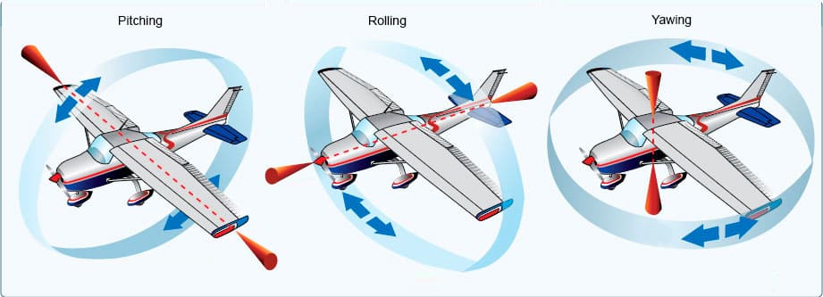
Additionally, rotation names are summarized in the figure below:
© 2025 Embention. All rights reserved.