3. Operation
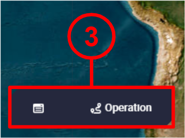
The Operation toolbar is composed by 3 'parts': Operation Panel, Operations and Operation actions. However, in the figure above there is no Operation actions part because there was no Veronte Autopilot 1x connected.
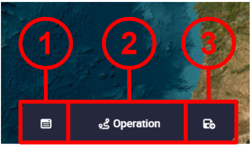
In the figure below, users can see these 3 'parts' when an Autopilot 1x is connected:
-
Operation Panel: Here the user can customize operation elements related to the operation, carry out some simple calibrations such as calibration of atmosphere, wind, DEM, etc., and manage complementary telemetry.
-
Operations: Users shall be able to export the operation loaded into the autopilot or import a different one and load it into the autopilot.
- Operation actions: These are actions related to when changes are applied to the operation/mission, such as Revert, Save, Reload and Upload changes. This 'part' is only available when a Veronte Autopilot 1x is connected. In addition, when a change is made, the other actions (Revert, Save and Reload) appear.
Operation Panel
This menu is divided into 3 different functionalities: manage operation elements in the Customize tab, simple calibrations in the Calibrations tab and manage complementary parameters in the Complementary Telemetry tab.
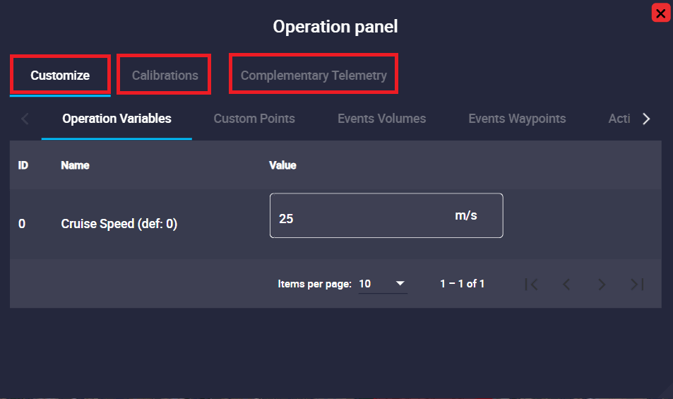
All parameters included in this panel are explained in detail in the following sections.
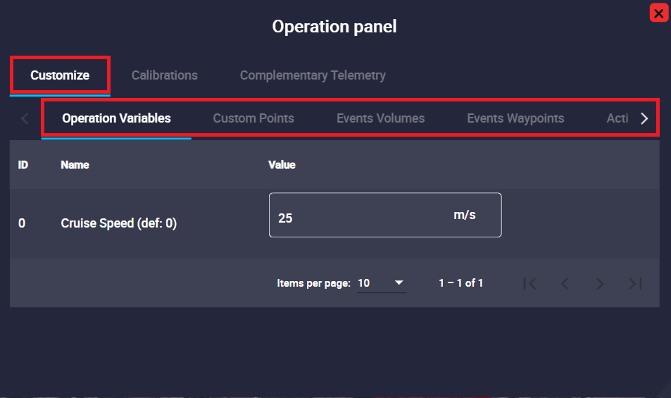
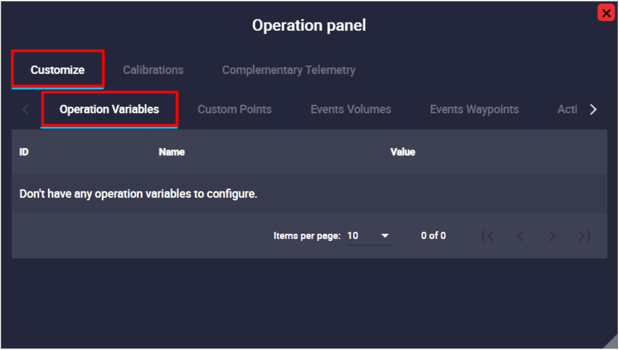
Customize
In this part of the menu users can find all the operation elements used during the operation and mission: Operation Variables, Custom Points, Events Volumes, Events Waypoint, Action Waypoints, Marks, Runways, Spots, Initial position UAV and Operator position.
If users wish to link a mark, custom point, prism, etc., to one of these variables, it is first necessary to define (rename) them in the UI menu of the 1x PDI Builder software, as described and explained in the corresponding section of the 1x PDI Builder manual, click here to access it.
Operation Variables
Operation Variables are configurable values, postitions and directions that can vary depending on the mission.
Important
Not setting the value of an operation variable may raise errors during the operation.
Examples of Operation Variables can be:
- Mission duration
- Cruise speed
- Flight level
- Takeoff and landing direction
- Home point
- Start of route
Their main advantage is that it is not necessary to access Veronte Autopilot configuration to modify them. In this way, the operator can modify certain parameters without the need of having access to the entire configuration.
As explained above, operation elements must be created while building a Veronte Autopilot configuration. So, when a new Operation Variable is created, a new field will appear in the operation variables tab:
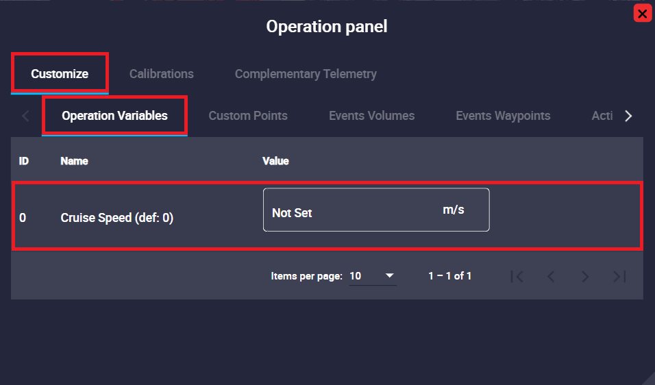
After this, the value of this variable can be defined using this menu.
The user simply clicks on the value cell, enters the desired new value and saves the change (![]() button, this is explained in the Save operation section below).
button, this is explained in the Save operation section below).
Below is an example of how to save changes locally and then upload them to the device:
Users should note that these Operation Variables can have minimum and maximum ranges defined in their configuration in the 1x PDI Builder software.
-
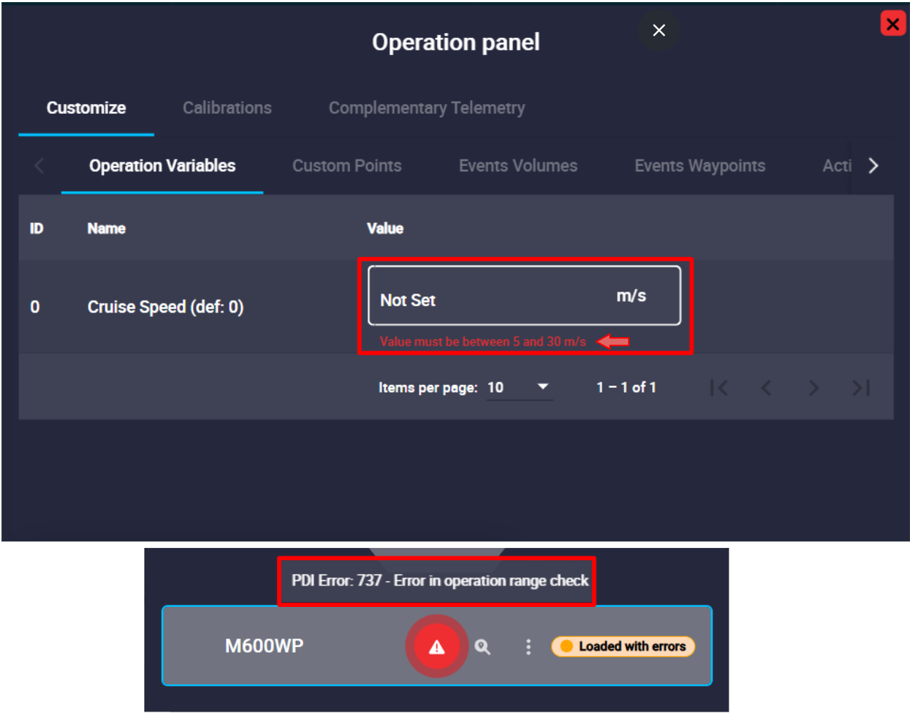
When the Operation Variable has a range already configured:
-
It is mandatory to set a value in the Operation Panel, i.e. the value cell cannot be empty. Otherwise, the PDI error:737 will be shown in the Platform panel.
Operation Variable error: Value Not Set -
The value that users enter here must be within the defined range, otherwise, they will not be able to save it and the software will automatically convert it to the closest value of the defined range (minimum or maximum value of the range). In addition, an error message will be displayed in the cell indicating the range.
Operation Variable error: Value not in range
-
-
When the Operation Variable does not have a range configured in 1x PDI Builder software, setting a value is an option, not a requirement. If any value is entered, the value cell will display "Not Set".
Furthermore, units can be changed in Veronte Ops, if they have been defined 1x PDI Builder software.
Warning
Although it is possible to modify operation elements during the flight, this practice is not recommended.
Whenever changing values during an operation, make sure that no potential risk to flight safety is involved.
Custom Points
A Custom point is an operation element that can be linked to a waypoint of the configured mission.
As explained above, an operation element only appears in this panel when it has been previously defined in the 1x PDI Builder software.
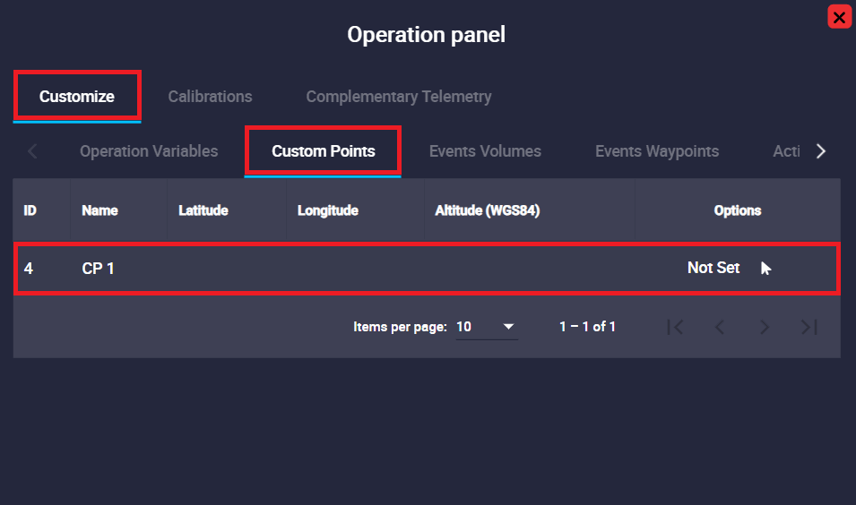
Therefore, as can be seen in the figure above, this Custom point has been defined in the autopilot configuration, but is not yet configured.
To configure it, it is necessary to click on the ![]() icon to link this Custom point to a waypoint of the mission. An example is shown below:
icon to link this Custom point to a waypoint of the mission. An example is shown below:
Once, the Custom point is linked to a waypoint, the following options will appear in the operation panel:
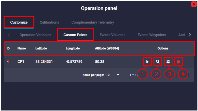
- ID: Custom point identification number.
- Name: Name of this Custom point defined in the 1x PDI Builder software.
- Coordinates: Latitude, longitude and altitude (WGS884) of the selected point.
- Options: These are configuration options of the Custom point:
- Select in map: To link the Custom point to a different waypoint, click here and select it on the map.
- Search: By clicking here, Veronte Ops will center and zoom in on the area of the map where this Custom point is defined.
- Edit options: This option allows the user to manually edit the position of the Custom point. Its configuration is the same as for a waypoint (a detailed explanation of this has been described in the Waypoint - Mission section of this manual).
- Remove reference: The user can remove the Custom point configuration by clicking here.
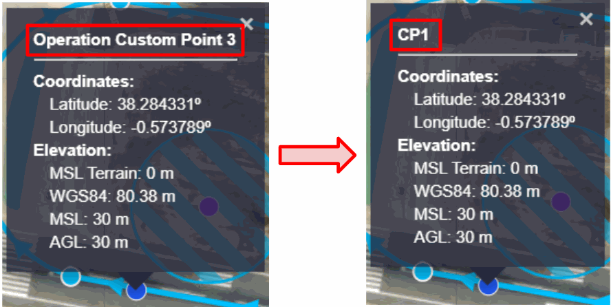
Moreover, by clicking on the linked waypoint, it will appear with the name of the configured Custom point:
Events Volumes
Set of volumes that assign events to Prisms, Cylinders, and Spheres.
These operation elements, Prisms, Cylinders and Spheres are detection volumes that can be linked to prisms, cylinders or spheres of the configured mission.
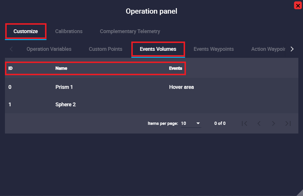
In the image above, the user can identify that there is a prism already defined and associated with an event, a sphere defined but without an associated event, and that there is no cylinder defined or associated to an event.
If the user wants to define cylindrical or spherical volumes, this must be done in the 1x PDI Builder software, as described at the beginning of the Customize section. Then, to associated an event with a volume, the process to follow is explained in the Shape - Mission section.
The following information is displayed in the operation panel:
- ID: Event volume identification number.
- Name: Element identifier, this has been defined in the 1x PDI Builder software.
- Events: Here is displayed the list of any events that are linked to this element, such as triggers for automatic actions.
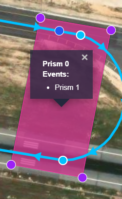
In addition, when clicking on the linked volume, its description will appear with the name defined by the user and the events linked to it will also appear:
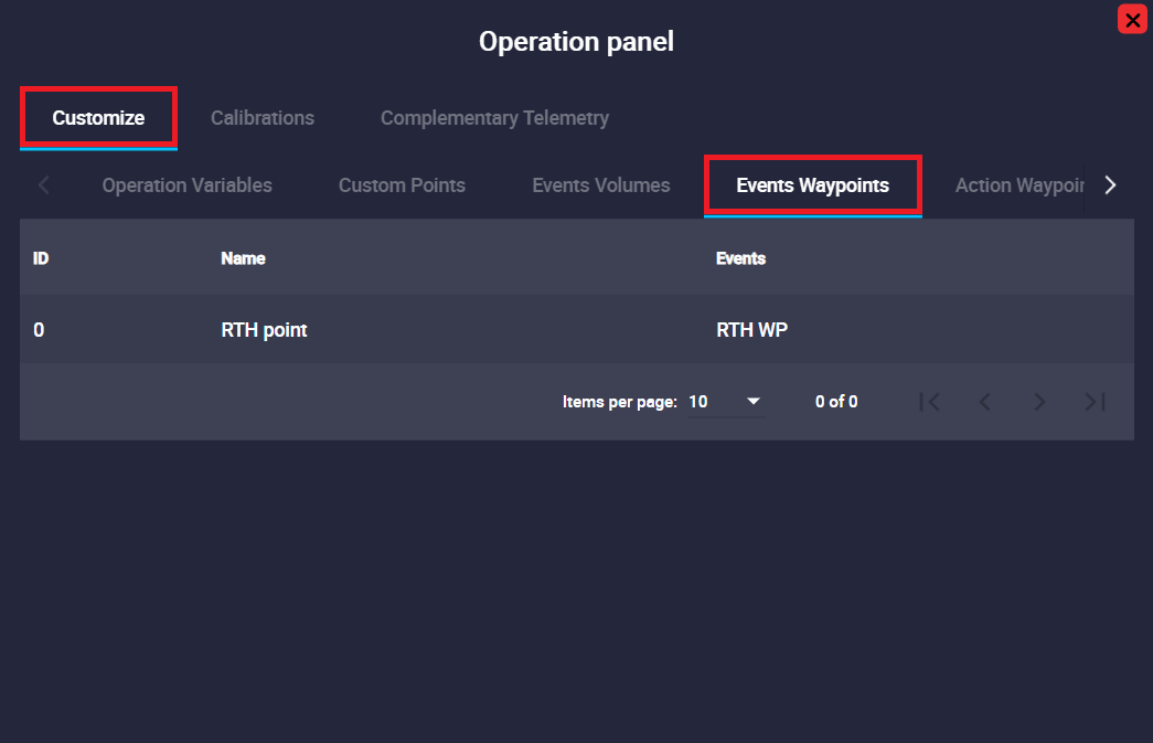
Events Waypoints
Events Waypoints allows for assigning properties and events to all waypoints belonging to this group.
This tab has the same options and works exactly the same way as the previous section (Events Volumes section).
In addition, when clicking on it, the Waypoint name defined by the user will appear in its description, as well as the events linked to it. An example is shown below:
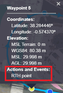
Action Waypoints
An Action Waypoints is a navigation points that are not just passing points, but are intrinsically linked to the execution of a complex action by the system (e.g., initiating a search pattern, releasing a payload).
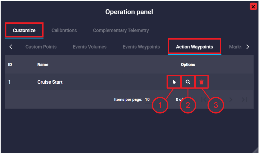
- Click Waypoint to set action: To link the Action Waypooint point to a different waypoint, click here and select it on the map.
- Serach: By clicking here, Veronte Ops will center and zoom in on the area of the map where this Waypoint is defined.
- Remove reference: The user can remove the Waypoint configuration by clicking here.
Marks
A Mark is an operation element that can be linked to a Mark (reference placed in a patch) of the configured mission.
The procedure for defining and configuring a Mark is the same as described above in the Events Volume section.
Once a Mark is configured, the following options will appear in the operation panel:
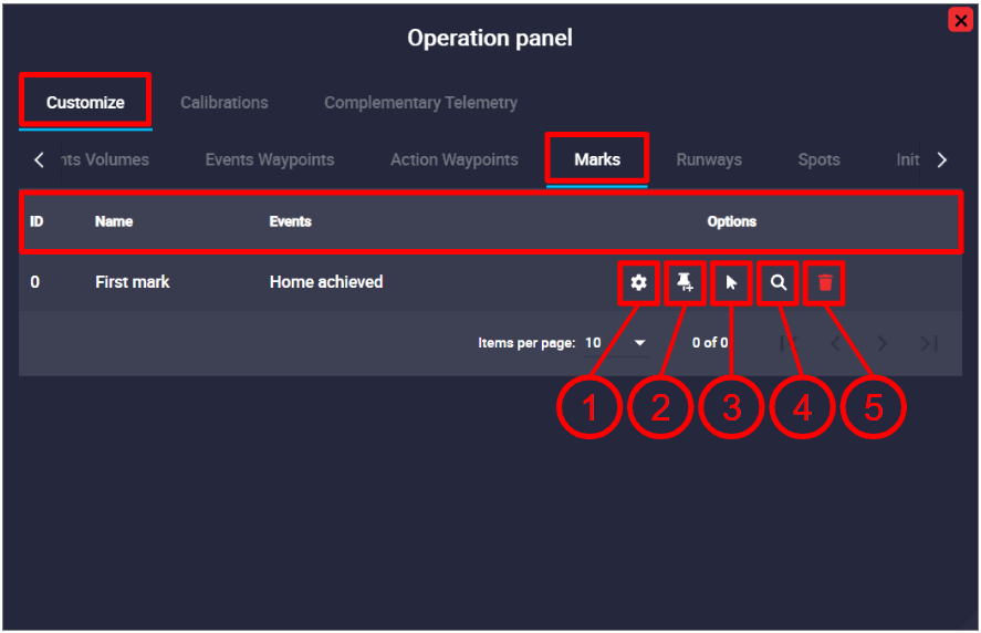
- ID: Mark identification number.
- Name: Element identifier, this has been defined in the 1x PDI Builder software.
- Events: Here is displayed the list of any events that are linked to this Mark, such as triggers for automatic actions.
-
Options: These are configuration options of the Mark:
- Search: By clicking here, Veronte Ops will center and zoom in on the area of the map where this Mark is defined.
-
Edit/Create:
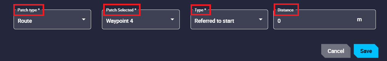
Marks - Edit -
Patch type: The user can select different flight guidance phases where the Marks will be placed: Approach, Climbing, Route, Taxi, VTol and Rendezvous. Except for Route patches, for the rest of the guidance phase, patches are generated when the user, or an automation, activates them. As the user cannot select these patches, as they cannot be generated initially, this option will automatically create the Marking on the selected patch.
-
Patch Selected: Most flight guidance phases have predefined patches with specific names. The user can select where the Mark will be placed on those patches. A table summarizing the available options is shown below.
-
Type: Right now the only possible option is "Referred to start" of the selected patch.
- Distance: Distance from the Mark to the start of the patch.
Climbing and Approach guidances are defined as follows:
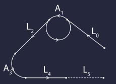
Marks - Approach patches 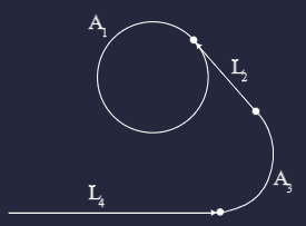
Marks - Climbing patches Approach L0/A1/L2/A3/L4/L5 Climbing A1/L2/A3/L4 Route 512 patches Taxi Taxi 0/Taxi 1 VTol VTol 0/VTol 1/VTol 3 Rendezvous Rendezvous 0/Rendezvous 1/Rendezvous 2 -
-
Create Mark in map and select: If the mark is not yet created in the mission, by clicking on this option, Veronte Ops will create it at the point on the map where the user clicks. In addition, Veronte Ops will automatically link this operation element to this newly created Marker.
Note
This option also appears although the Mark is not yet configured (linked to a created Mark).
-
Select in map: To link this operation element to a different Mark, click here and select it on the map.
- Remove reference: The user can remove the Mark configuration by clicking here.
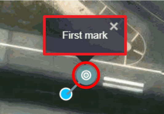
Moreover, if the event that is linked to the Mark has an associated icon, the icon will appear on that Mark. In addition, when clicking on it, its description will appear with the name defined by the user and the events linked to it will also appear. An example is shown below:
Runways
Runways are operation elements that can be linked to the runways of the configured mission.
Like all other operation elements, Runways have to be defined in 1x PDI Builder and then configured by selecting a runway from the map.
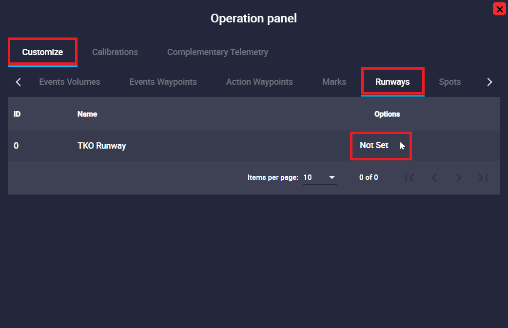
The following configurable options will then appear in the operation panel:
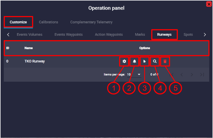
- ID: Runway identification number.
- Name: Element identifier, this has been defined in the 1x PDI Builder software.
-
Options: These are configuration options of the Runway:
-
Edit: By clicking here the user will be able to modify the runway settings. A detailed explanation of how to configure it can be found in the Runway - Mission section of this manual.
-
Configure Alarms: Alarms can be associated to Runways. A detailed explanation of how to configure them can be found in Runway - Mission section of this manual.
-
Click to map: To link this operation element to a different runway, click here and select it on the map.
-
Search: By clicking here, Veronte Ops will center and zoom in on the area of the map where this Runway is defined.
-
Remove reference: The user can remove the Runway configuration by clicking here.
-
Moreover, by clicking on the linked runway, it will appear with the name of the configured Runway:

If the user clicks on the Start, End or Loiter points of the Runway, they are also renamed:

Spots
Spots are operation elements that can be linked to the spots of the configured mission.
They function in the same way as the Runways operation elements:
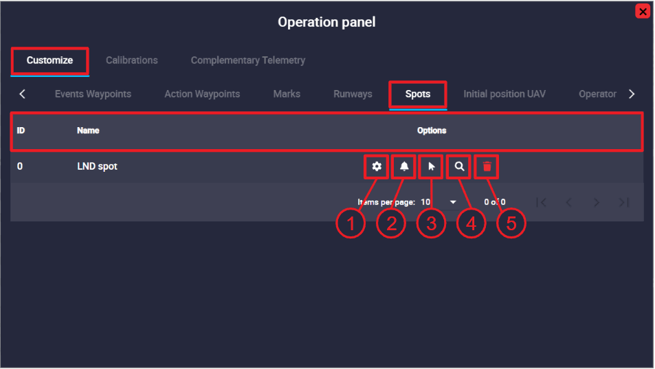
- ID: Spot identification number.
- Name: Element identifier, this has been defined in the 1x PDI Builder software.
- Options: These are configuration options of the Spot:
- Edit: By clicking here the user will be able to modify the spot settings. A detailed explanation of how to configure it can be found in Spot - Mission section of this manual.
- Configure Alarms: Alarms can be associated to Spots. A detailed explanation of how to configure them can be found in Spot - Mission section of this manual.
- Click to map: To link this operation element to a different spot, click here and select it on the map.
- Search: By clicking here, Veronte Ops will center and zoom in on the area of the map where this Spot is defined.
- Remove reference: The user can remove the Spot configuration by clicking here.
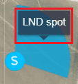
Moreover, by clicking on the linked spot, it will appear with the name of the configured Spot:
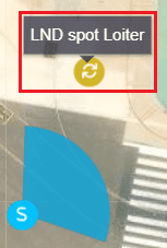
If the user clicks on the spot loiter point, it is also renamed:
Initial position UAV
It is a marker indicating the initial position of the UAV.
In addition, users can find and center this marker on the map, as well as show/hide it.
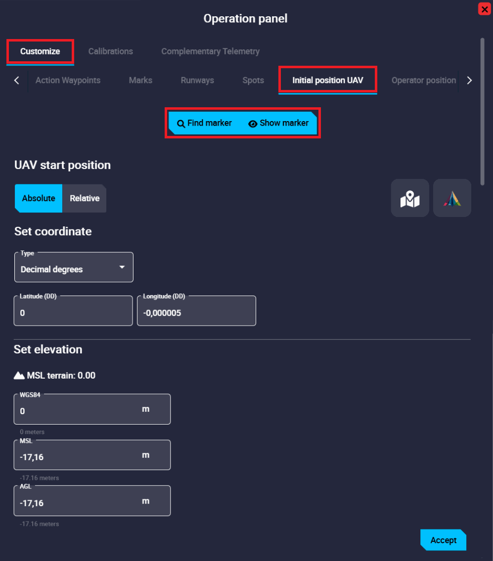
It is configured in the same way as waypoints. For a detailed explanatin of this, please refer to the Waypoint - Mission section of this manual.
After setting the position, it is necessary to click Accept and then Save and Upload the operation.
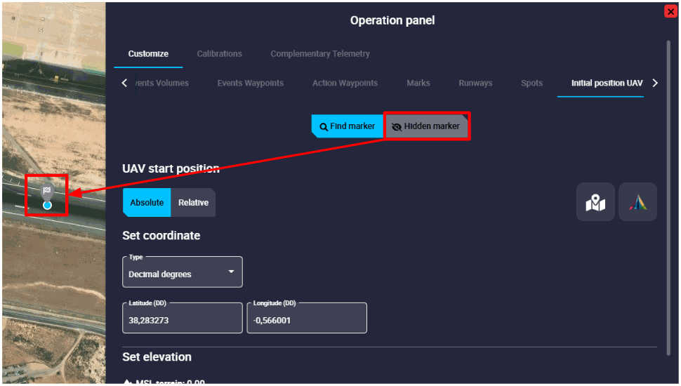
In the figure below, the marker is "shown" (as the hidden button appears):
Operator position
This tab enables the configuration of the Operator position.
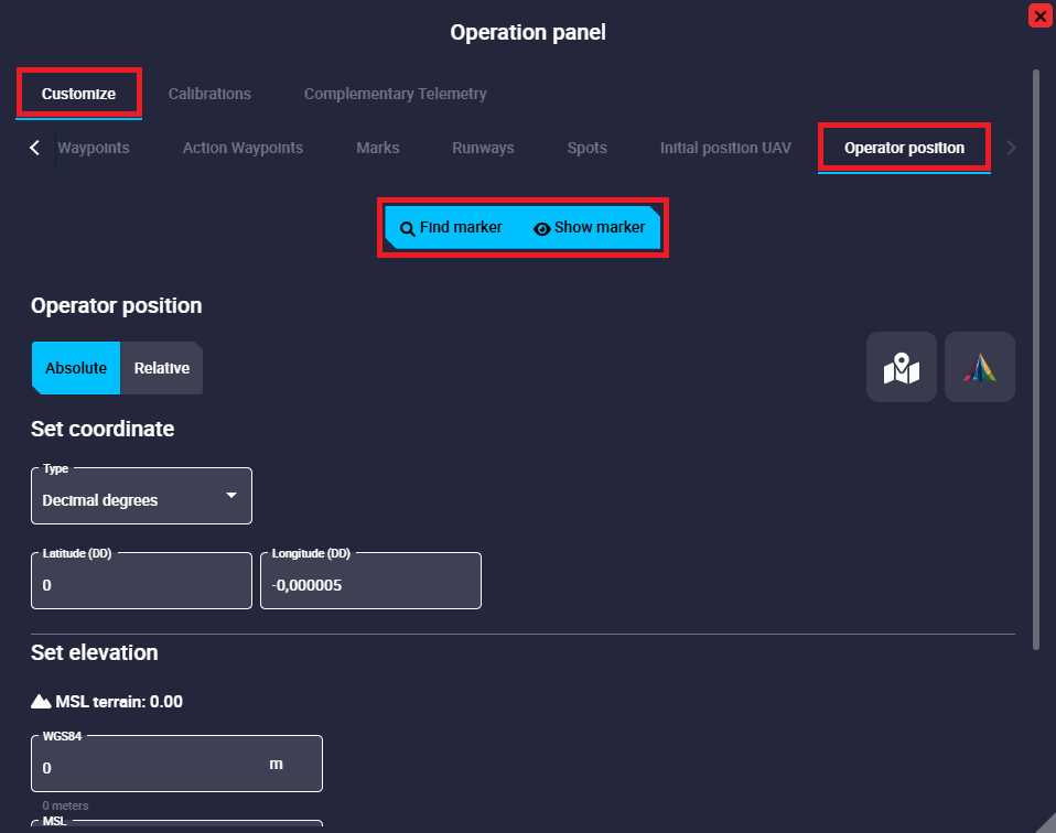
It is configured in the same way as waypoints. For a detailed explanatin of this, please refer to the Waypoint - Mission section of this manual.
After setting the position, it is necessary to click Accept and then Save and Upload the operation.
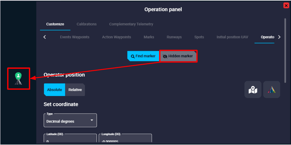
In the figure below, the marker is "shown" (as the hidden button appears):
Note
From the operator position defined in this panel, the distance allowed by the license to operate is calculated. Remember that Veronte Autopilot 1x has limited-operation depending on the license status. For more information on this limitation, please refer to the 1x Hardware Manual.
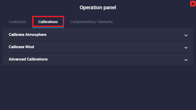
Calibrations
In this tab, the user can carry out simple calibrations during a standard operation. This way, there is no need of modifying the configuration or building a specific automation.
Note
Some of the following calibrations can also be triggered automatically using Automations.
Note
These calibrations will never modify the autopilot's current configuration: the changes are volatile, and will disappear once the system is rebooted.
Warning
To send any of these calibrations, it is necessary to click on the 'Send' button.
Calibrate Atmosphere
Calibration for MSL calculation with barometric pressure.
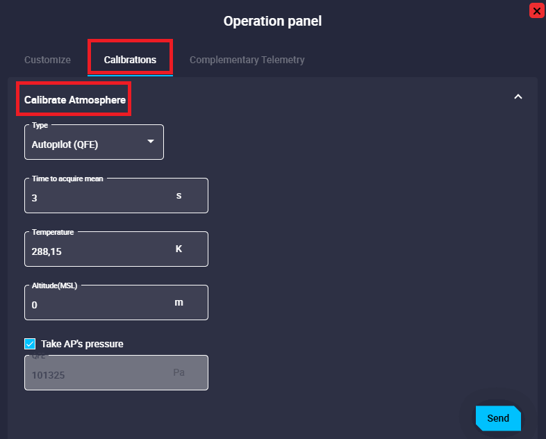
- Type: QFE and QNH options are available.
- Time to acquire mean: Specified time during which the static pressure is read from the static pressure sensor.
- Temperature: Outside air temperature.
- Altitude (MSL): Actual MSL altitude.
- Take AP's pressure: If enabled, static pressure will be selected from the autopilot measurement, otherwise users will have to enter it manually.
Wind Calibration
This command allows to enter initial values for wind state and start wind estimation algorithm.
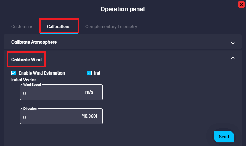
- Enable Wind Estimation.
- Init: By enabling it, an initial wind vector can be set to a faster convergence of the estimation.
- Wind Speed: Module of the initial wind speed.
- Direction: Argument/Direction of the initial wind speed.
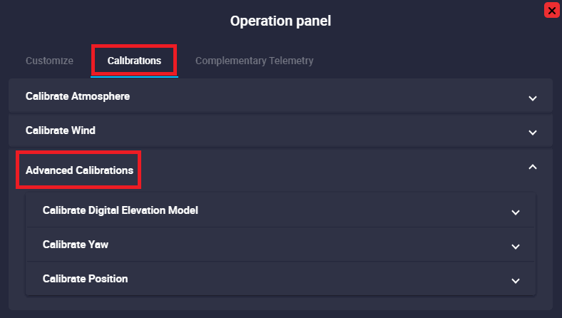
Advanced Calibrations
The following are the advanced calibrations that can be performed by the user during operation:
-
Calibrate Digital Elevation Model (DEM)
This calibration calculates the offset that the SRTM of the current point should have so that the estimated AGL results in the desired AGL (the one indicated in the calibration).
Warning
- This offset is only valid for the point where the DEM has been calibrated.
- Always perform this action on the ground, unless an accurate estimation of current AGL is available.
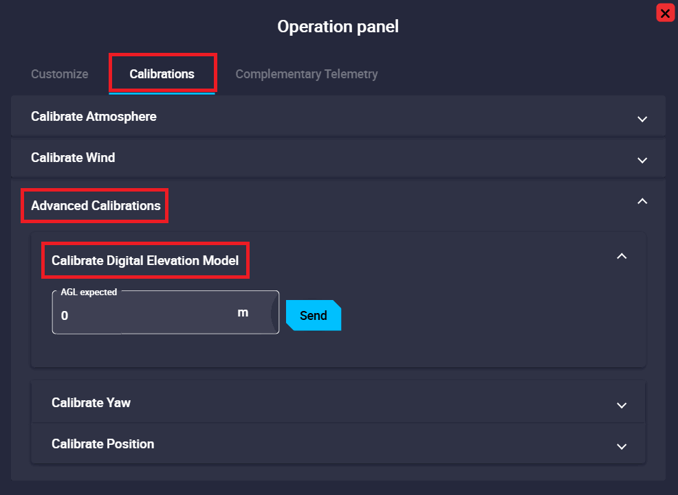
Advanced Calibrations - Calibrate DEM
-
Calibrate Yaw
Allows to manually modify the Yaw Navigation state.
Warning
If there is any Yaw sensor active (i.e. Magnetometer), this command will not work since it will be automatically overrided.
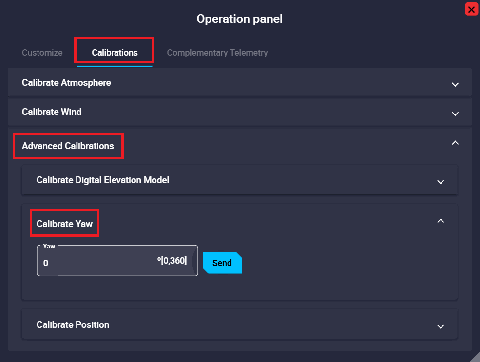
Advanced Calibrations - Calibrate Yaw -
Calibrate Position
Allows to manually modify the Position Navigation state.
The configurable parameters of the position calibration are the same as for configuring the position of a waypoint. So they have already been described in detail earlier in the Waypoint - Mission section of this manual.
Warning
If there is any absolute positioning sensor active (i.e. GNSS), this command will not work since it will be automatically overrided.
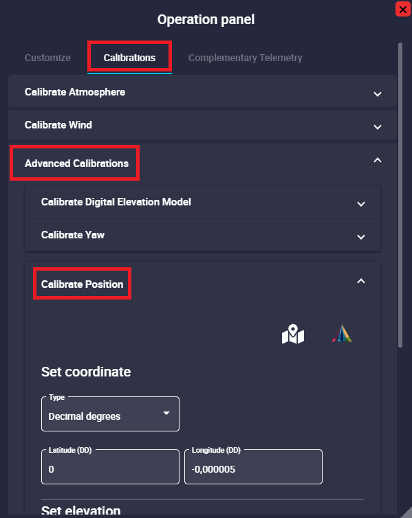
Advanced Calibrations - Calibrate Position
Complementary Telemetry
The Complementary Telemetry panel enables users to include extra flight data. While telemetry is primarily configured in 1x PDI Builder, further parameters can be added directly within Veronte Ops.
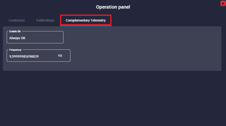
- Enable Bit:
- Always OK: Enable Complementary Telemetry.
- Always Fail: Disable Complementary Telemetry.
- Frequency: Frequency at which the telemetry data is transmitted from the autopilot to Veronte Ops. It is possible to choose between Hz, MHz, and kHz.
Important
The complementary vector telemetry always runs at a fixed frequency of 10 Hz (not configurable), and variables are sent uncompressed. Therefore, it is recommended to add the variables to the 'Data to Vapp' telemetry vector to configure the desired frequency, variable compression/uncompression, etc.
Operations
By clicking here, it is possible to modify the operation.
The following options are available:
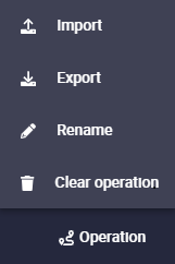
- Import: The user can import an operation, the available formats are:
ZIP,KMLandGEOJSON. - Export: The current operation can be exported, the available formats are:
ZIP,KMLandGEOJSON. - Rename: The user can rename the operation as desired.
- Clear operation: Clicking here will delete the selected operation.
Note
When a configuration is saved in the 1x PDI Builder software, the following message will appear to inform the user that there is a new operation loaded in the Autopilot 1x:
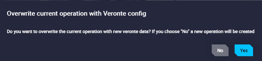
- If the user does not select anything, after 10 seconds this message will disappear and a new operation will be created.
- If the user selects NO, a new operation will also be created, as described in the message.
- If the user selects YES, no new operation will be created and the changes saved in the 1x PDI Builder software will be applied to the current operation, i.e. the current operation will be overwritten.
Operation actions
![]() Revert Operation changes
Revert Operation changes
- When a change is made, it is possible to revert it by pressing this button. This is only possible if the changes have not yet been saved.
![]() Save Operation
Save Operation
- Local saving of the mission.
![]() Reload
Reload
- The Reload command reverts the operation to the last saved version.
Warning
This operation is only available if the mission has not been uploaded to the device.
To apply any change to the device, it is necessary to save it by pressing this button.
![]() Upload to '(Platform name)'
Upload to '(Platform name)'
- To update the operation loaded on the autopilot with the new saved changes, click on this button.
-
If there is no change to upload to the operation configuration, the following message will appear:

Nothing to Save in '...'
© 2026 Embention. All rights reserved.