Hardware Installation
Since Veronte Serial is a small PCB, electrical connections are made by soldering cables. Once cables are welded, the device can be wrapped in a shrinking tube.
Important
Cables from 22 AWG to 24 AWG are required.
Pinout
Pins are physically marked on the board as the following drawing shows:
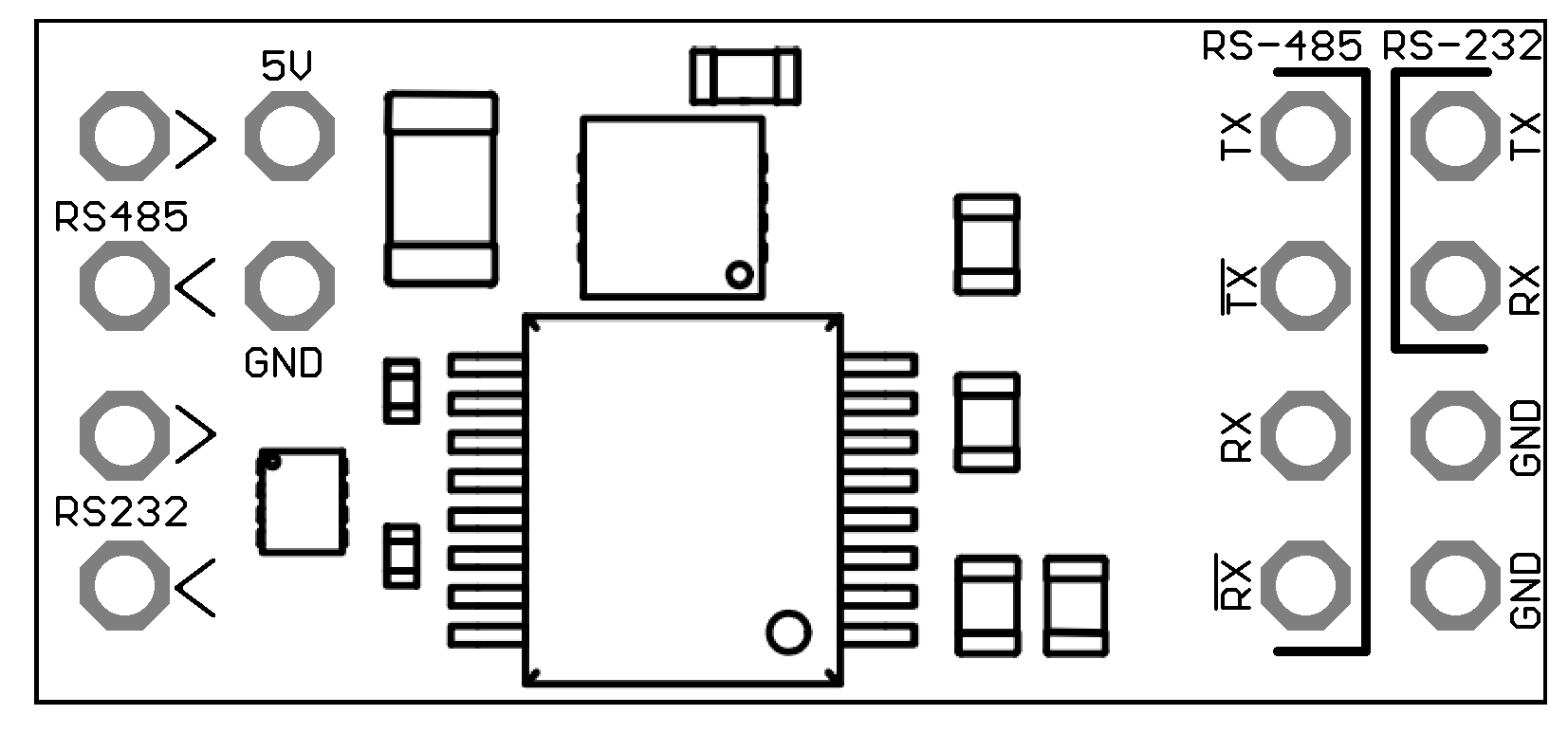
Danger
Ground pins are common. They MUST be connected to the same ground in order to prevent short circuits.
Domain |
Pin |
Description |
|---|---|---|
Power supply |
5 V |
Power supply of 5 V (with a margin range from 2.3 to 6.5 V). |
GND |
Ground. |
|
RS-232 |
> |
UART input for RS-232 channel. |
< |
UART output for RS-232 channel. |
|
TX |
Output signal (transmitter). |
|
RX |
Input signal (receiver). |
|
RS-485 |
> |
UART input for RS-485 channel. |
< |
UART output for RS-485 channel. |
|
TX |
Non-inverted output (transmitter). |
|
RX |
Non-inverted input (receiver). |
|
__
TX
|
Inverted output (transmitter). |
|
__
RX
|
Inverted input (receiver). |