Stick
Veronte Autopilot REx is compatible with joysticks that use PPM, CAN bus, USB, Serial, etc.
1. PPM Connection
If the PPM level is 3.3V, the following Autopilot REx pins can be used:
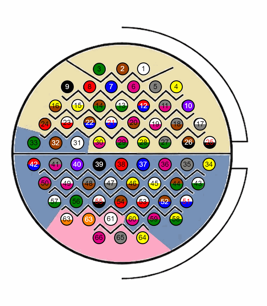
| Connector | PIN | Signal | Type | Use for PPM stick |
|---|---|---|---|---|
| J1 | 17 | J1_DIGIN_A | INPUT | PPM signal input (recommended on Dev Harness jack) |
| J1 | 29 | J1_GND_IO | GROUND | PPM ground (used on Dev Harness jack) |
| J1 | 25 | J1_DIGIN_B | INPUT | Alternative PPM signal input |
| J1 | 26 | J1_GND_IO | GROUND | Ground for J1 digital inputs |
| Dev Harness REx 2.0 reference: Jack connector is wired to J1 pin 17 (J1_DIGIN_A) and J1 pin 29 (J1_GND_IO), as defined in Hardware Installation. | ||||
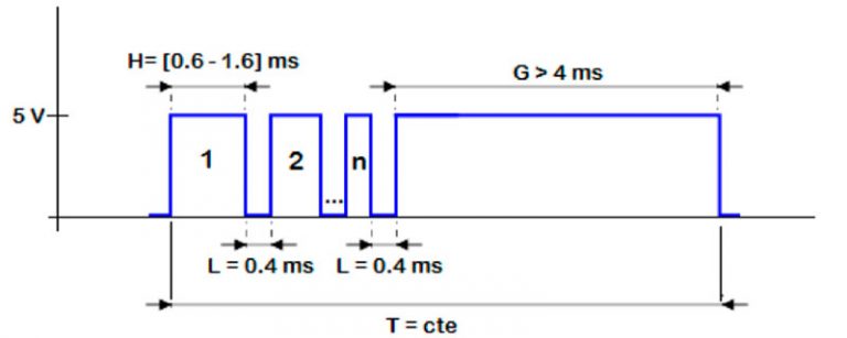
Caution
PPM signal must be into the Veronte Autopilot REx voltage ranges. Some joysticks may need an adaptation board, please ask our team to check compatibility.
Connector for harness is provided with 3.5 mm stereo plug connector as follows:
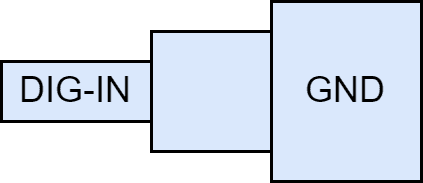
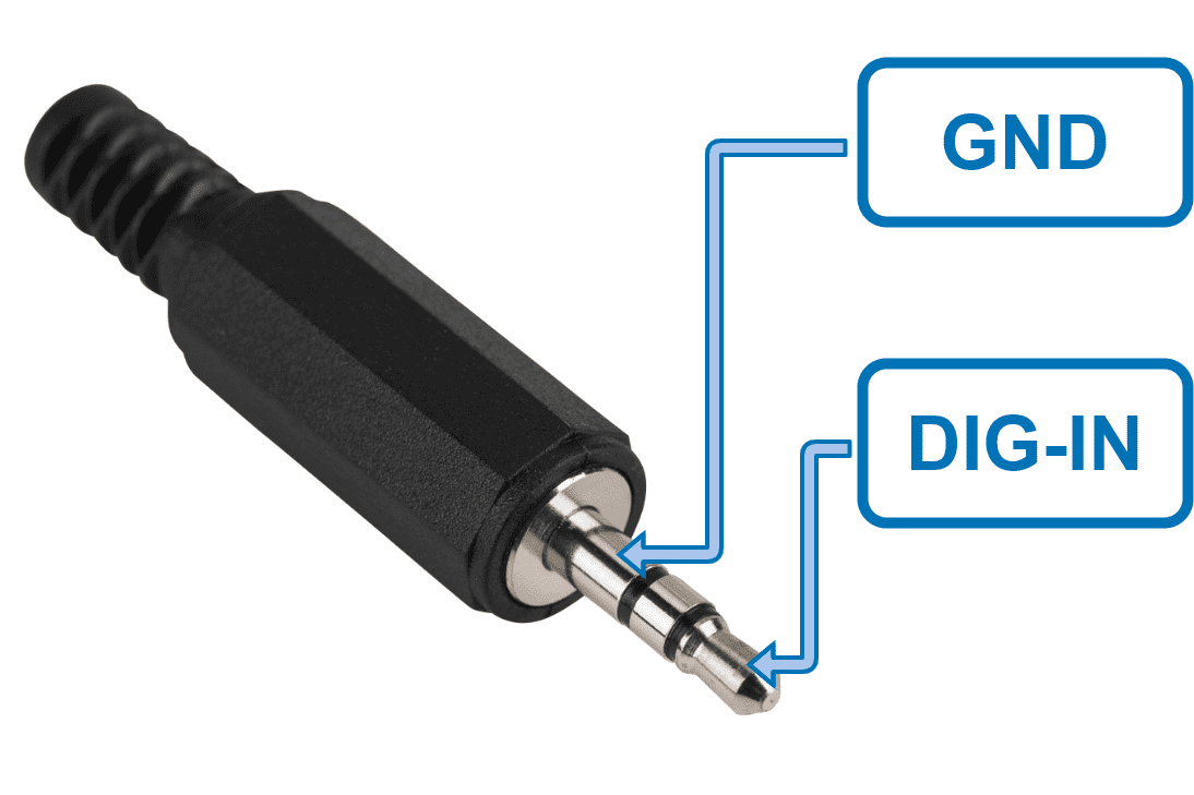
- To use the joystick with PPM in the system, connect the PPMout of the trainer port to a digital input of Veronte Autopilot REx and configure that digital input according to the PPM Stick - Integration examples section of the 1x PDI Builder user manual.
2. CAN Connection
For joystick integrations using CAN bus, use the following pins from Hardware Installation:
| Connector | PIN | Signal | Type | Use for CAN stick |
|---|---|---|---|---|
| J1 | 9 | J1_CAN_MUX_A_P | CAN BUS | CAN A positive (muxed) |
| J1 | 16 | J1_CAN_MUX_A_N | CAN BUS | CAN A negative (muxed) |
| J1 | 24 | J1_CAN_MUX_B_P | CAN BUS | CAN B positive (muxed) |
| J1 | 33 | J1_CAN_MUX_B_N | CAN BUS | CAN B negative (muxed) |
| J1 | 23, 48 | J1_CAN_GND | GROUND | CAN ground |
3. Serial Connection
For joystick integrations using Serial, use RS232 and/or RS485 according to your joystick interface:
| Connector | PIN | Signal | Type | Use for Serial stick |
|---|---|---|---|---|
| J1 | 60 | J1_RS232_TX_A | OUTPUT | RS232 A TX |
| J1 | 65 | J1_RS232_RX_A | INPUT | RS232 A RX |
| J1 | 61 | J1_RS232_TX_B | OUTPUT | RS232 B TX |
| J1 | 66 | J1_RS232_RX_B | INPUT | RS232 B RX |
| J1 | 39, 54 | J1_GND_RS232 | GROUND | RS232 ground |
| J1 | 52, 58 | J1_INA_485_P / J1_INA_485_N | INPUT | RS485 A input pair |
| J1 | 64, 59 | J1_OUTA_485_P / J1_OUTA_485_N | OUTPUT | RS485 A output pair |
| J1 | 43, 35 | J1_INB_485_P / J1_INB_485_N | INPUT | RS485 B input pair |
| J1 | 51, 44 | J1_OUTB_485_P / J1_OUTB_485_N | OUTPUT | RS485 B output pair |
| J1 | 45, 47 | J1_GND_RS485 | GROUND | RS485 ground |
- When using a USB joystick, the software installation with Autopilot REx is detailed in the USB joystick - Integration examples section of the 1x PDI Builder user manual.
- For joysticks with signals different from PPM or USB, read the Virtual Stick - Integration examples section of the 1x PDI Builder user manual.
© 2026 Embention. All rights reserved.