Hardware Installation
Mechanical
R24F OEM Assembly
M4 screws are recommended for mounting. In saline environments such as coastal and oceanic, the screw material must be stainless steel.

R24F OEM assembly
To weld the cables read the Pinout section of this manual
R24F Assembly
First of all, unscrew the box and the PCB.
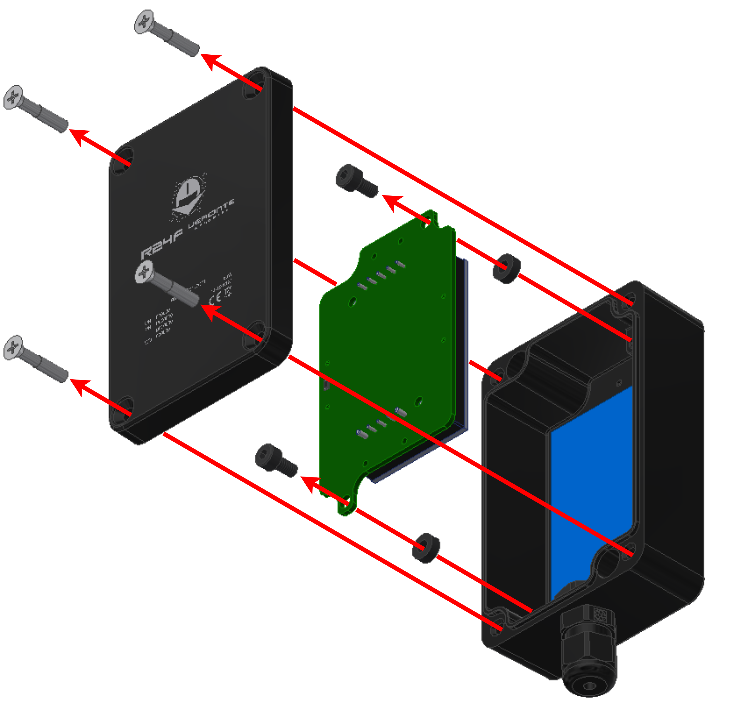
Unscrew R24F
Then, weld the cables to the PCB following the Pinout section of this manual.
Next, pass the cables through the cable gland and screw the PCB back.
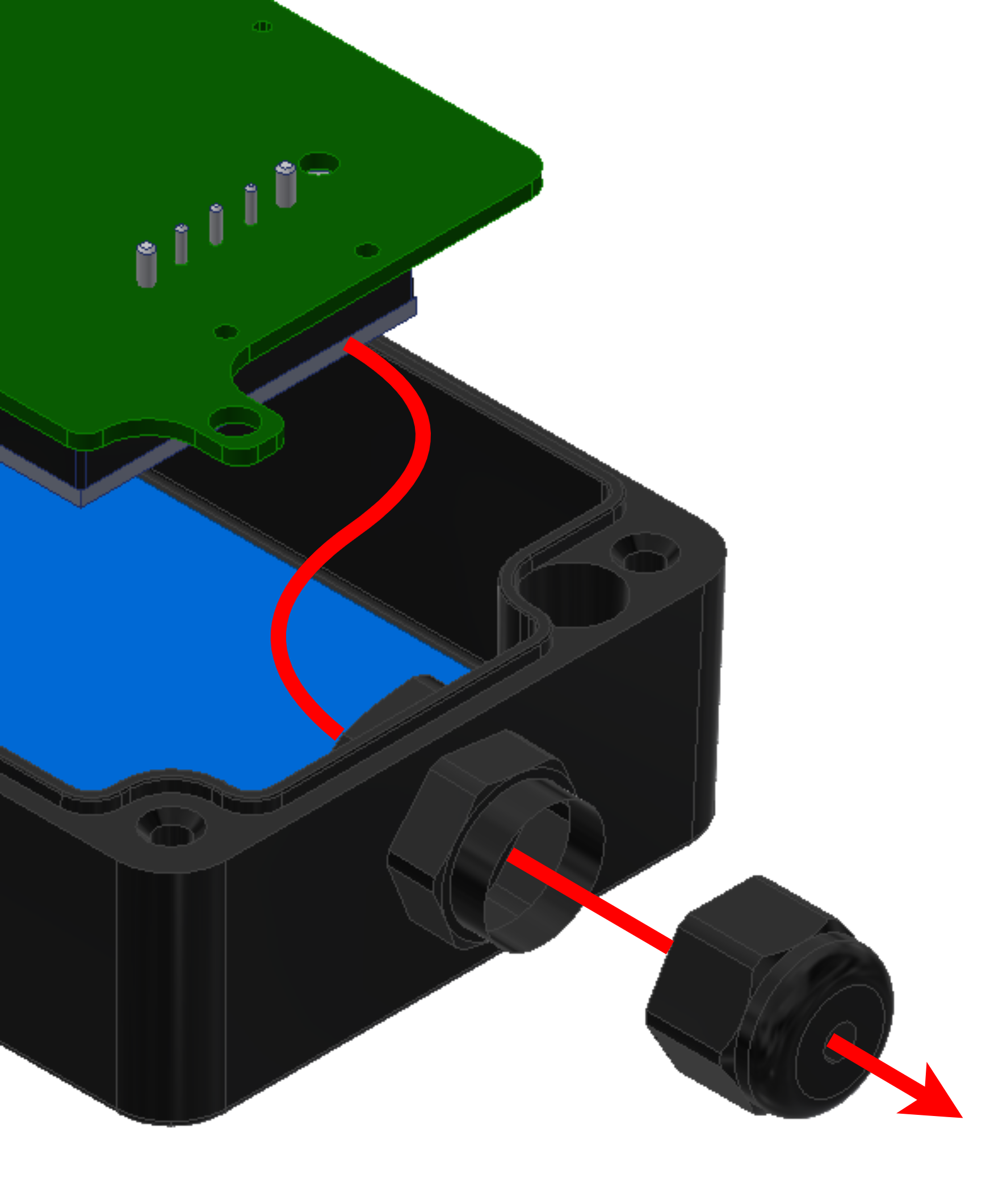
Cables assembly
For mounting, M3 screws are recommended. In saline environments such as coastal and oceanic, the screw material must be stainless steel.

R24F assembly
Finally, screw the box back.
Pinout
The following diagram shows the holes to weld each cable.
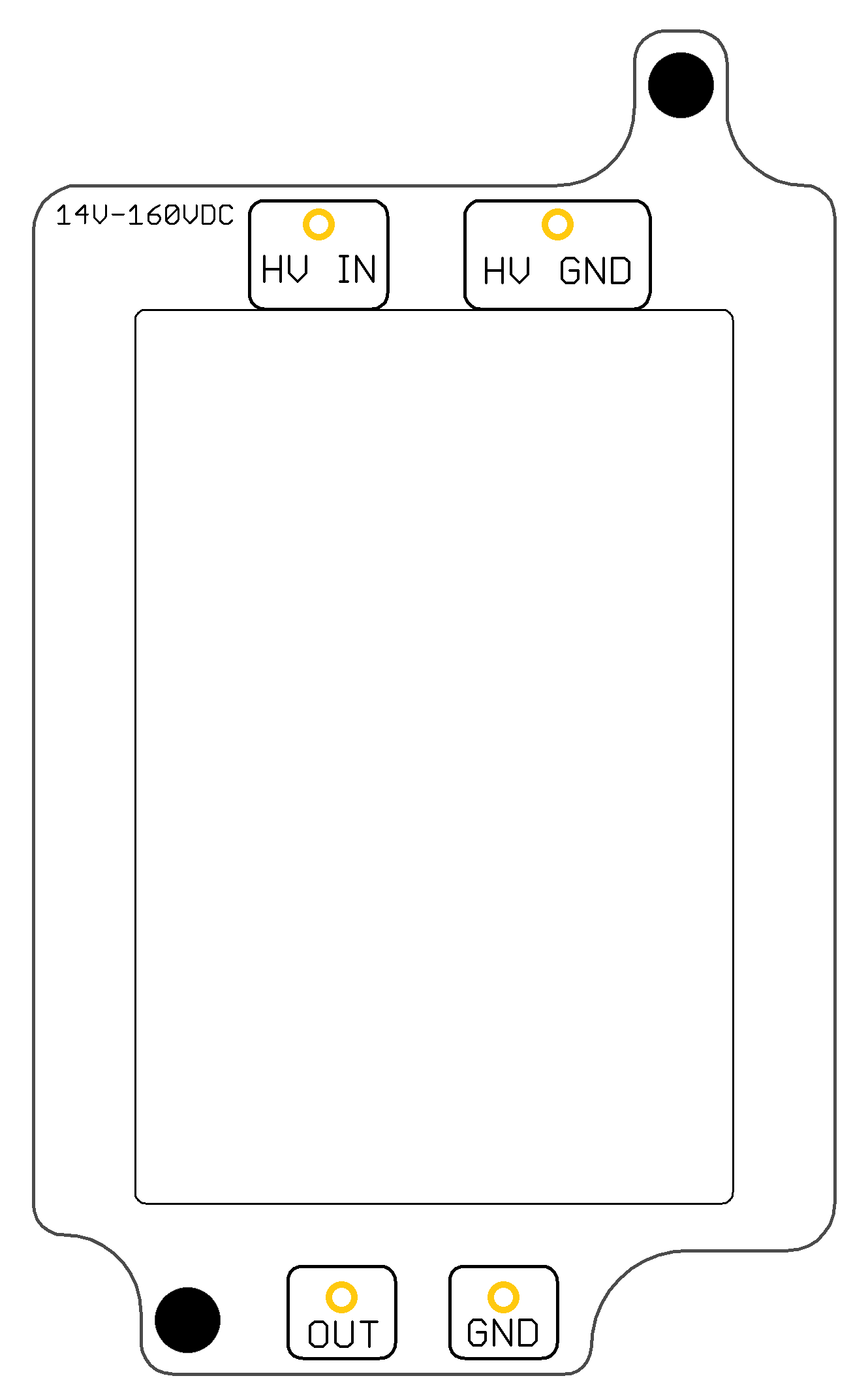
HV IN: Positive of the input power supply (from 14 to 160 V DC).
HV GND: Ground of the input power supply.
OUT: Positive of the output voltage (24 V DC).
GND: Ground of the output supply.
Note
Grounds are not common.