Technical
Main Features
- Ready for operation
- Compatible with Veronte LCS or third party computers
- RTK & differential barometer base
- Wifi and Ethernet communications
- Expansion bay (free space for customer electronics installations)
- Easy maintenance
- 2 hours of battery life
- Battery over discharge protection
Part list
The system consists of a multiple components listed below.
- Veronte PCS Control Station Unit.
- Pole and wall mounting accessories.
- Foldable mast.
- Connection harness.
- Veronte Control station power source (euro plug). This power supply is worldwide compatible if the power cable is changed.
- 5 m ethernet extension cable.
- 5 m joystick extension cable.
- Rugged transport case.
- Omnidirectional antenna - 2.4G Hz and 3.2d Bi.
- Datalink (not always, depending on variant).
- Amplifier (not always, depending on variant).
- Cable power extension connector - 5m - Amphenol 6P.
The Veronte PCS Control Station Unit is built with a Veronte Autopilot 1x inside to manage communications.
Electrical Specifications
| PCS DC input | 14 to 24 VDC |
| PCS power | 30 W to 80 W (depending on version) |
| Power supply AC input | 180-264 VAC 50-60 Hz |
| Battery type | LiFePO4 |
| Battery capacity | 10 Ah |
| Battery operation time | 2 hours typically (depending on version) |
| Wifi | 2.4GHz and 5GHz configurable Wifi output |
| RF2 and RF3 Frequencies | 400MHz, 900MHz or 2.4GHz (depending on version) |
| RF2 and RF3 Impedance | 50 Ohm |
| GNSS 1 | Integrated GNSS antenna. 40dB Gain, covering GPS/QZSS L1, GLONASS G1, Galileo E1, BeiDou B1, as well as SBAS |
| GNSS 2 | SMA female connector for secondary GNSS antenna |
| Expansion bay I/O | RS-232, CAN, PPM, FTS and Ethernet. Pins 1 to 8 have a nominal current limit of 6 A for. Pins 10 to 16 have a nominal current limit of 4A. |
| External I/O | x2 CAN 2.0 interfaces, x1 CAN FD Interface, x1 Ethernet 1000BASE Interface, x2 RS-485 Interfaces, x2 FTS Interfaces, x1 RS-232 Interface, x1 I2C Interface, x7 PWM Outputs, x1 PPM Signal, x4 Analog Inputs, x1 GPIO. |
| Expansion bay power outputs | 3.3 V / 5 A, 5 V / 5 A, 12 V / 8 A and 24 V / 6 A |
Mechanical Specifications
| PCS Weight | 5.7 kg max |
| PCS + Pole Weight | 10.2 kg max |
| Operating temperature | -20 to 60 °C |
| Environmental proteciton | IP54 |
| Transport case | Rugged plastic case, quad track wheels, pressure purge valve, side handles and carry handle |
Dimensions
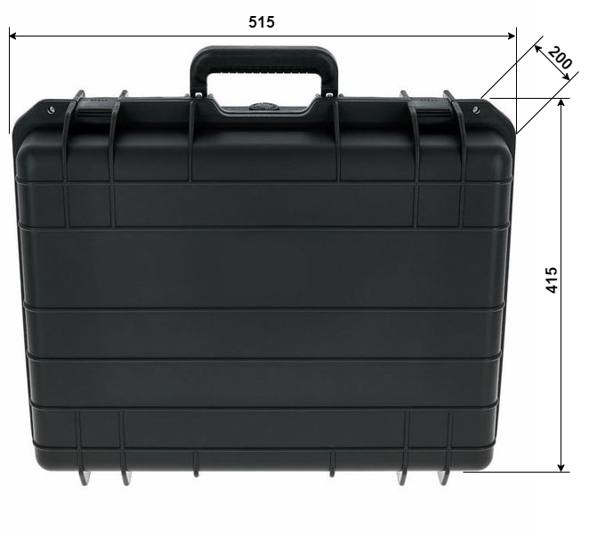
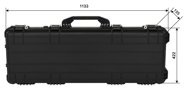
Below you can find a measurements drawing for the PCS.
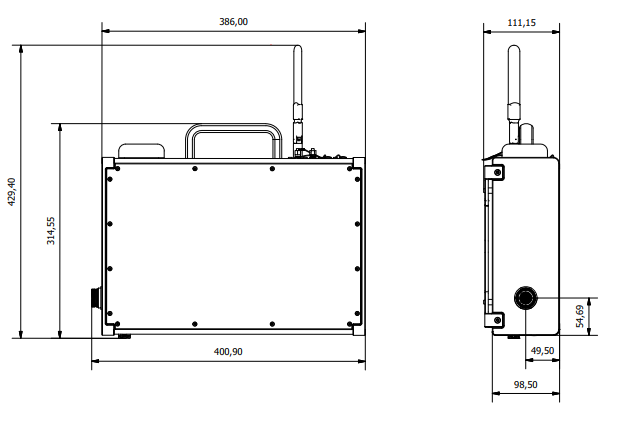
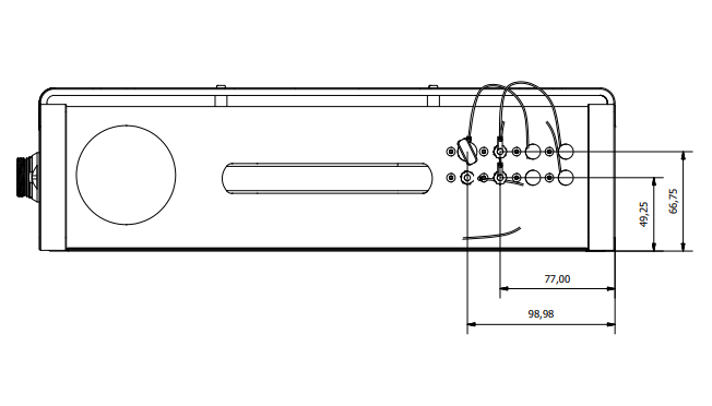
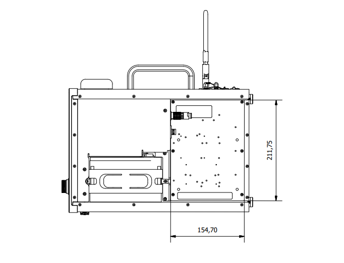
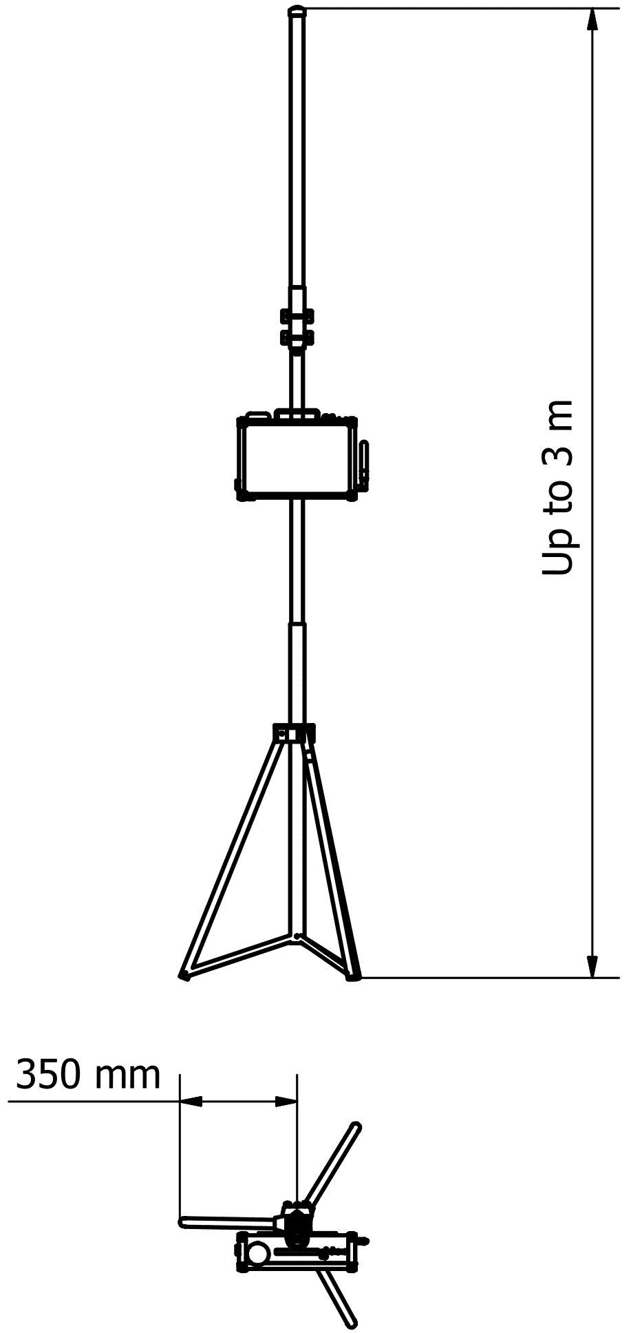
Veronte PCS is supplied together with a telescopic foldable mast that can be extended up to 3 m. The maximum and the minimum dimensions of the system are shown below.
Interfaces
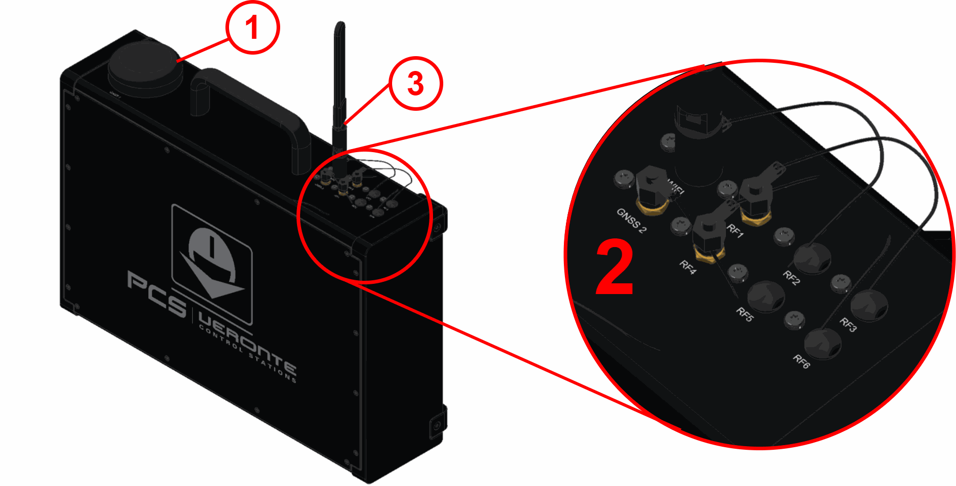
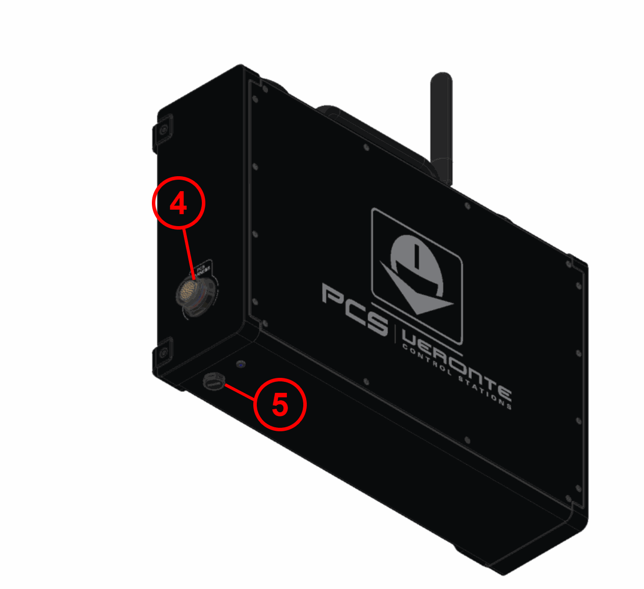
Connector Layout
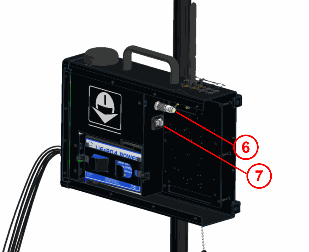
| Index | Connector |
|---|---|
| 1 | Integrated GNSS antenna |
| 2 | SMA connectors, see SMA Connections table to know what they are connected to |
| 3 | Wifi antenna connector (SMA female RP) |
| 4 | PCS Harness connector. |
| 5 | Automatic pressure purge |
| 6 | Connector for Expansion Bay |
| 7 | Ethernet connector |
Mating Connectors
| Index | PCS Connector | Mating Connector |
|---|---|---|
| 2 | SMA connectors (SMA female RP) | SMA Male. Antennas depending on the Datalink Kit are detailed below |
| 3 | Wifi antenna connector (SMA female RP) | SMA Male. Antenna (RUTX10000000) (Embention reference P011834) |
| 4 | Main Connector HEW.LM.368.XLNP |
Mating connector: FGW.LM.368.XLCT (Embention reference P005550) Mating harnesses available on demand:
|
| 6 | Expansion Bay Connector EGG.2B.316.CLL | Mating connector: Veronte Connector PCS 16P (FGG.2B.316.CLAD72Z) (Embention reference P008623) |
| 7 | Ethernet connector RJ45 | Standard RJ45 connector |
Datalink Kits
Embention offers different Datalink kits to add a radio modem to the PCS. They are available with different device configurations in order to fit all operational requirements from each application. Each Datalink Kit variant is described below. To know how to install and configure each radio, read Datalink Kit Installation and Configuration section of this manual.
| Veronte Control Stations: PCS Datalink | Part number | Radio modem | Frequency | Amplifier | RF Power | Video | Antenna datasheets |
|---|---|---|---|---|---|---|---|
| Kit A (SDL24 2.4GHz - 1W - TM/TC) 1.0 | P015753 | Veronte SDL24 | 2.4 GHz | No | 1 W | No | HG2415U-PRO |
| Kit B (SDL09 900MHz - 1W - TM/TC) 1.0 | P015754 | Veronte SDL09 | 900 MHz | No | 1 W | No | FG9023 |
| Kit C (SDL04 400MHz - 1W - TM/TC) 1.0 | P015755 | Veronte SDL04 | 400 MHz | No | 2 W | No | BC70-1G |
| Kit H (MH 2.4GHz - 10W - Video & TM/TC) 1.0 | P015756 | MH2RA | 2.4 GHz | Yes | 10 W | Yes | HG2415U-PRO |
| Kit I (MH 900MHz - 10W - Video & TM/TC) 1.0 | P015757 | MH9RA | 900 MHz | Yes | 10 W | Yes | HG906U-PRO |
| Kit J (SDL24 2.4GHz - 10W - TM/TC) 1.0 | P015758 | Veronte SDL24 | 2.4 GHz | Yes | 10 W | No | HG2415U-PRO |
| Kit K (SDL09 900MHz - 10W - TM/TC) 1.0 | P015759 | Veronte SDL09 | 900 MHz | Yes | 10 W | No | FG9023 |
| Kit L (SV 2x2 2.4GHz (10W) - Video + TM/TC) 1.0 | P011403 | Silvus 4200 | 2.4 GHz | No | 10 W | Yes | FG24008 |
| Kit M (SV 4x4 2.4Ghz (20W) - Video + TM/TC) 1.0 | P011405 | Silvus 4400 | 2.4 GHz | No | 20 W | Yes | FG24008 |
| Segregated FTS Trigger A (Datalink SDL24 2.4GHz - 1W - TM/TC) 1.0 | P011815 | Veronte SDL24 | 2.4 GHz | No | 1 W | Yes | HGV-2458-05U |
| Segregated FTS Trigger A (Datalink SDL09 900MHz - 1W - TM/TC) 1.0 | P011817 | Veronte SDL09 | 900 MHz | No | 1 W | Yes | HGV-2458-05U |
© 2026 Embention. All rights reserved.