Configuration
After installing, MC24 PDI Builder the main menu will show as follows:
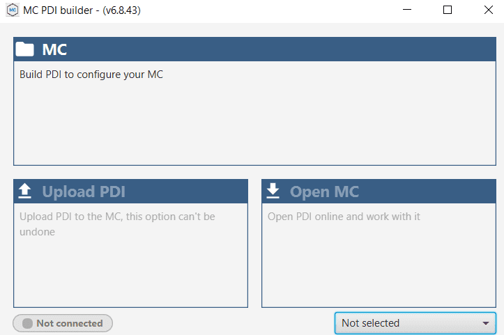
MC: Create a new PDI set of files to be saved and exported.
Upload PDI: Upload a previously created set of files to the current motor controller flash memory.
Open MC: Edit the current MC settings.
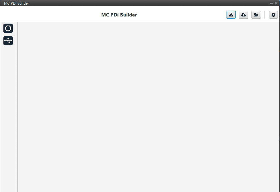
At this point, the user can either create its own configuration offline by clicking on “MC PDI Builder” or start editing the one that is already loaded to the controller by clicking on “Open MC”. The same menu will pop up:
Open Loop Ramp
This menu sets the start ramp before engaging the closed loop control. There basically three parameters:
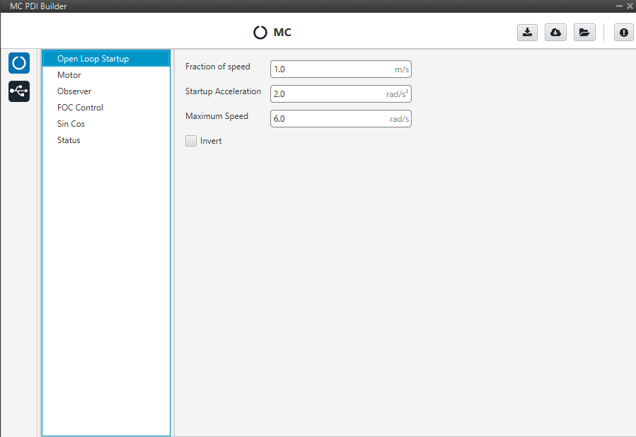
Speed fraction: fraction of maximum speed (third field) to be reached before changing to closed loop.
Startup Accelaration: angular acceleration to reach maximum speed. In rad/s^2.
Maximum Speed: final speed to be reached before closing the control loop. In rad/s.
Invert: Change spining direction of the rotor. This is the main way to invert the motor direction and will also affect the control and closed loop functionalities.
Motor
This tab sets all the physical parameters of the motor that will be used with Veronte MC. These are:
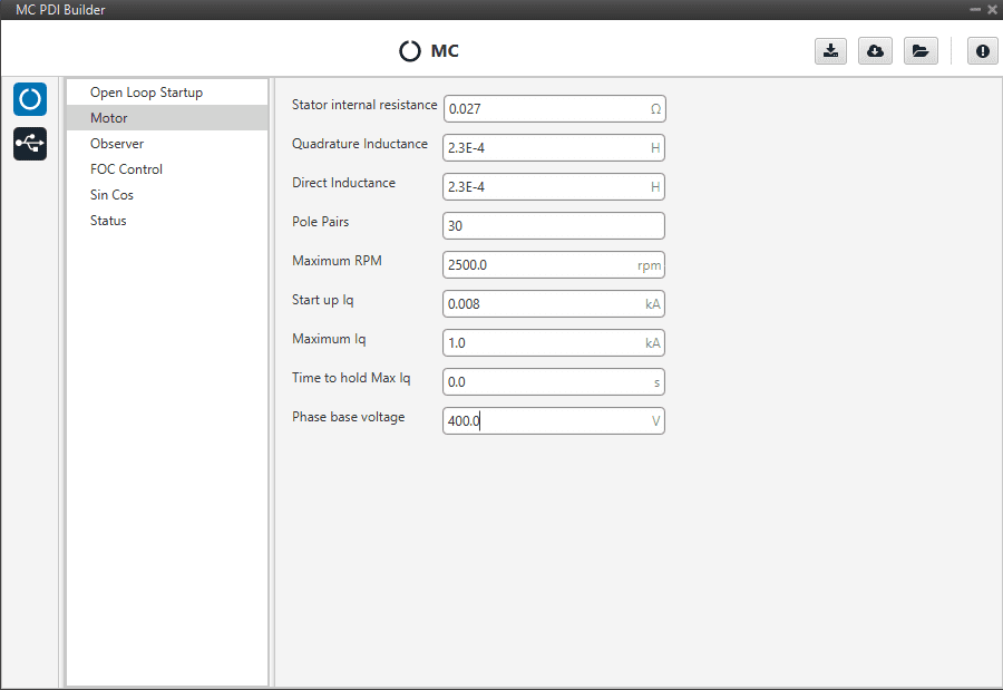
Stator internal resistance: resistance that usually specified in datasheets. Expressed in Ohms.
Quadrature Inductance: usually called “Lq”. Expressed in Henries (H).
Direct Inductance: usually called “Ld”. Expressed in Henries (H).
Pole pairs: number of poles divided by two. For instance, if your motor has 42 poles, you must input 21 here.
Maximum RPMs: maximum RPMs motor can reach in combination with your propeller. This parameter is only used to determine the equivalence between the maximum command (PWM or CAN) and the commanded RPM in speed closed loop mode.
Startup Iq: quadrature current used to start the motor.
Maximum Iq: maximum quadrature current the speed control loop can command to the quadrature current control loop. Please refer to FOC background section for further reference.
Time to hold Max Iq: maximum time to hold the previous value before going to off.
Phase base voltage: nominal working voltage of each phase.
FOC (Field Oriented Control) Background
In order to achieve better dynamic performance, a more complex control scheme needs to be applied, to control the PMSM motor. With the mathematical processing power offered by the microcontrollers, we can implement advanced control strategies, which use mathematical transformations in order to decouple the torque generation and the magnetization functions in PMSM motors. Such de-coupled torque and magnetization control is commonly called rotor flux oriented control, or simply Field Oriented Control (FOC).
The Field Oriented Control consists of controlling the stator currents represented by a vector. This control is based on projections which transform a three phase time and speed dependent system into a two co-ordinate (d and q co-ordinates) time invariant system. These projections lead to a structure similar to that of a DC machine control. Field orientated controlled machines need two constants as input references: the torque component (aligned with the q co-ordinate) and the flux component (aligned with d co-ordinate). As Field Orientated Control is simply based on projections the control structure handles instantaneous electrical quantities. This makes the control accurate in every working operation (steady state and transient) and independent of the limited bandwidth mathematical model.
A basic scheme for the FOC is represented as follows:
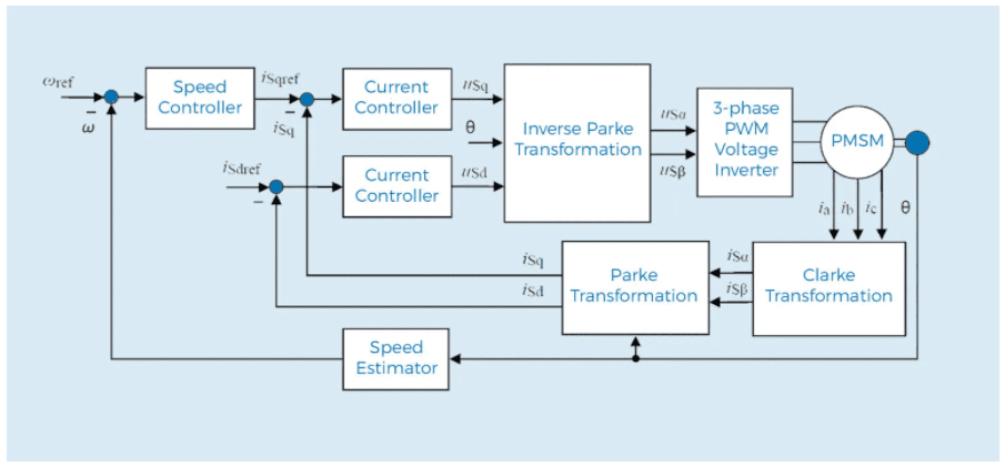
As it can be seen, there some key pieces in this algorithm:
Park/Clark transform: these output a two co-ordinate time invariant system and a outputs a two co-ordinate time variant system respectively. As mentioned before, this is part of the process of getting two scalar values from a three phase time dependent system.
PI Controllers: there are three of them: two to control quadrature current and direct current (torque and flux) and one to control speed. This last one is placed as the one that controls Iq PI (cascade control) which means that in order to get more speed the system will command more torque (or Iq).
Speed estimator: this block is able to estimate, first electrical angle and then mechanical speed, from currents and voltages using the so-called “Sliding Mode Observer” (SMO) algorithm.
The main dificulty of this control proposal is to tune these three PI controller although in most cases both current PI are exactly the same due to PMSM properties. In addition, it is necessary to tune SMO algorithm as it depends on motor properties.
This last part is optional(but highly recommended due to sensor failures) in case an external sensor is used such as a hall effect sensor or a SIN/COS sensor.
Sensorless Observer / Estimator
Once the basis of the FOC are covered, the rest of the features of this MC can be explained. This tab covers the observer parameters. The observer that is implemented has an ON/OFF controller that gets the estimated electrical angle. This electrical angle is later derived to find the angular speed:
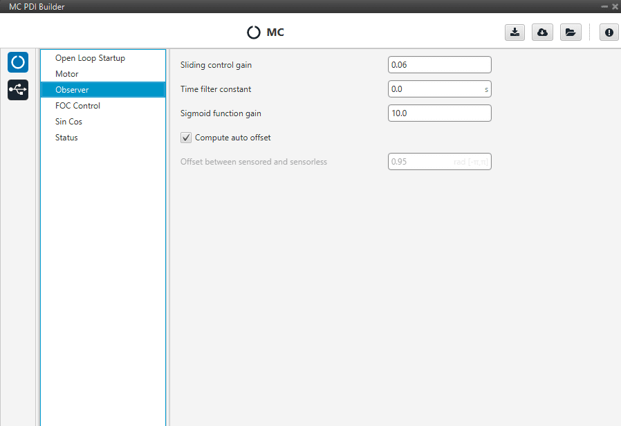
Sliding Control Gain: this is the main gain of observer. To guarantee algorithm stability this value has to be bigger than absolute value of Back EMF (ElectroMotive Force) in alpha/beta axes.
Time filter constant: speed calculation has a first order filter. This is the time constant of this filter. The lower value, the lower filtering.
Sigmoid function gain: this gain is to smooth the bang bang control of SMO.
Offset between sensored and sensorless: this value aligns osberver signal to virtual motor signal. It is very important to go from open to close loop. This value has to match with variable “offset of virtual motor” of MC in open loop.
Compute auto offset: activate auto-calculation of previous offset value to close loop.
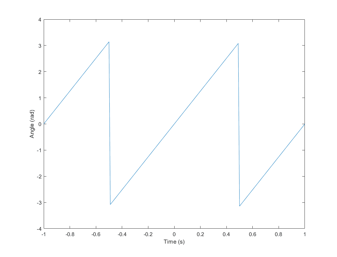
After parameters tuning, electrical angle from SMO should look like this:
Warning
It is recommended to tune this estimator even if an external sensor is used for feedback (sensored control). As it will be described in the next section, the control will automatically jump in case the primary source of feedback fails to a sensorless control.
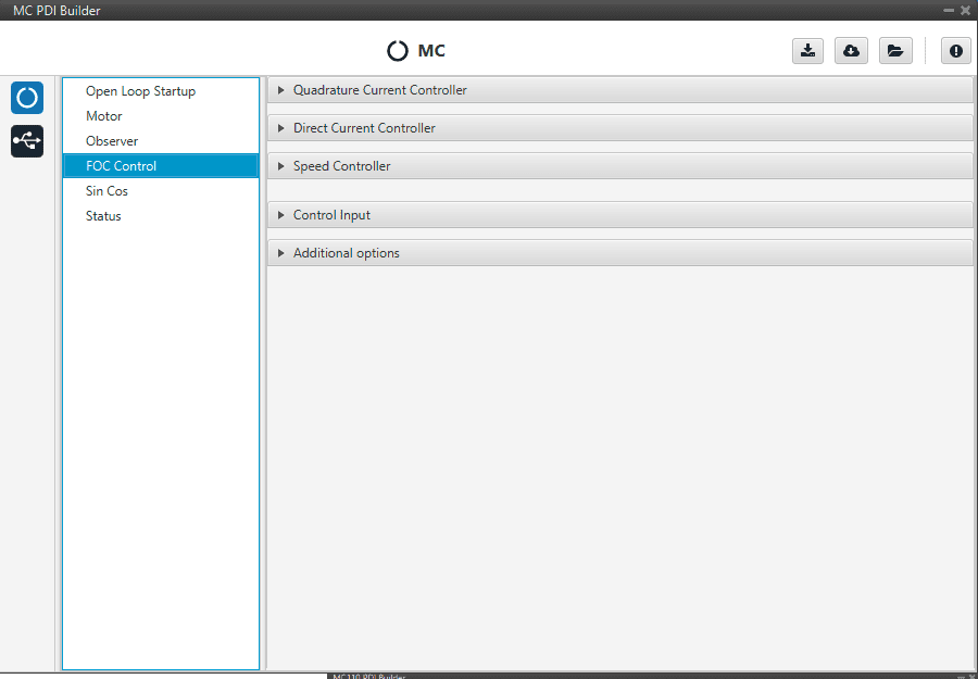
FOC Control
This is the main control menu, here all parameters regarding FOC control are set. As mentioned before, the basic blocks that define the FOC control are three PI (Proportional, Integral controllers). First, both current PI (quadrature and direct) are defined. Each current axis (q and d) has two gains configuration: open and close loop. Usually,open and closed loop gains are equal, but it could be that the motor behaviour requieres different current tunning. In addition, quadrature and direct PI gain configuration are usually equals, but it will depend on if the motor parameters are equals in both axes.
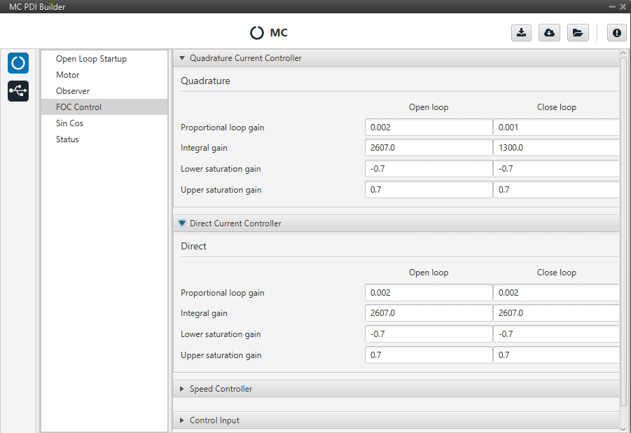
The form of the PI is the classical parallel form:
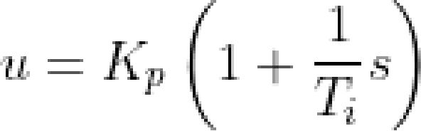
Where integral gain refers to the quotient 1/Ti. Lower and upper saturation gain are the limits at which the PI limit its output. In this case, as it is illustrated in FOC background, these outputs are Vq and Vd.
Equally, the speed controller can be set here as shown below. In this example this PI controller is limited to be output 7 A.
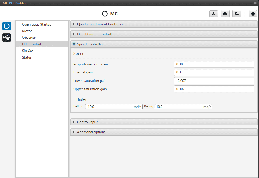
In addition, there is a rate limiter that could be used in case the slope needs to be limited with the input comand. Please note that is expressed in rad/s.
Control input allows the user to select the input source and several extra parameters such as:
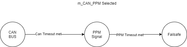
CAN Timeout: whenever this timeout is met, the control input will be changed to the next option if available. If none of them is available, it will end up in failsafe mode.
PPM Timeout: same as before, but in this case the only option after this one is failsafe.
Value for Fail Safe: value between 0 and 1. It will be written in case none of the previous options is available.
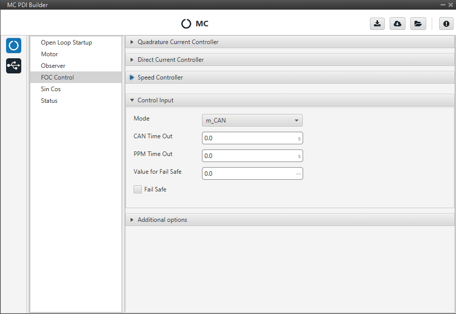
The input flow is the following in case the mode m_CAN_PPM is selected:
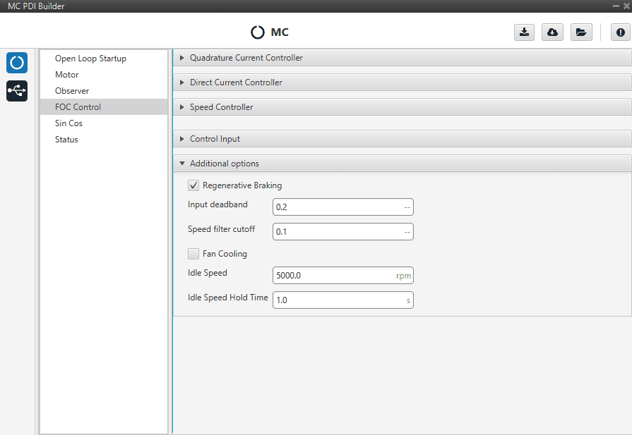
There are some additional options than can be set under FOC control menu:
Regenerative Braking: activates regnerative braking feature which is basically consisting of thoughing some current back to battery whenever the motor is loosing speed (it uses the kinetic energy to charge de battery). This not recommended in case the power side is not connected to a battery.
Input deadband: this is the value that defines when to start moving the motor. For example, it might be wanted to be different from zero in case an RC stick outputs around 0.2 of duty cycle by default.
Note
In case CAN Bus is used to command (see CAN I/O section), this deadband can be calculated as (desired deadband RPM)/(maximum RPM).
Speed filter cutoff: cutoff frequency (in Hz) that will be applied to filter Hall effect sensors and SIN/COS sensors only.
Fan Cooling: this option activates a PID control in a cooling fan to achieve the normal working temperature.
Idle Speed: minimum speed of motor to go OFF.
Idle Speed Hold Time: if speed is lower than idle speed and this time is reached, motor go OFF.
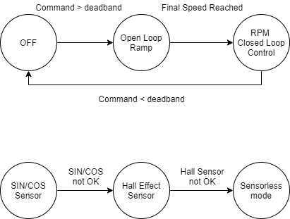
Finally, a state machine diagram is presented to clarify how the control and feeback sources work:
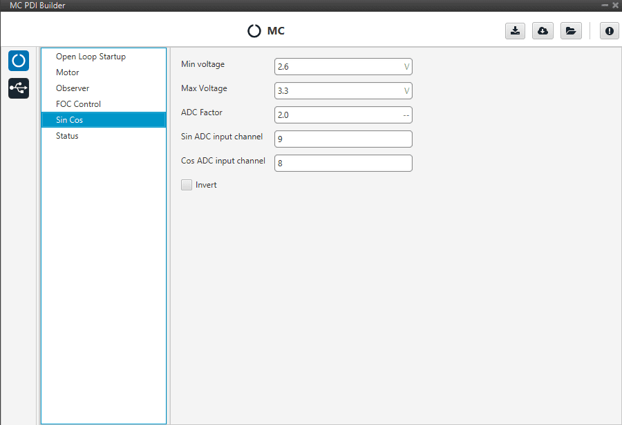
SIN/COS Sensor
In case an external SIN/COS sensor needs to be used as a source of feedback of electrical angle/velocity the main interface to do it is though ADC inputs. This menu allows the user to customize the main characteristics of its sensor:
Min Voltage: minimum voltage of the signal. Measured in Volts (V).
Max Voltage: maximum voltage of the signal. Measured in Volts (V).
ADC factor: a factor multiplying what is read from the ADC port, specially useful if a voltage divider (or any other signal level adaptor) is installed.
Sin ADC input channel: ADC channel at which the SIN signal is connected.
Cos ADC input channel: ADC channel at which the SIN signal is connected.
Invert: inverts the resulting electrical angle. Useful to correct installation inversions.
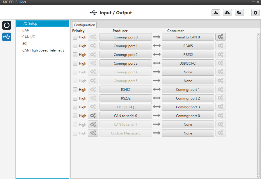
I/O Setup
This panel is used to stablish the mapping of ports and the duties they are performing. The layout and principles of function of this feature are common in all Veronte products, a complete explanantion can be found in the I/O Setup section of 1x PDI Builder user manual.
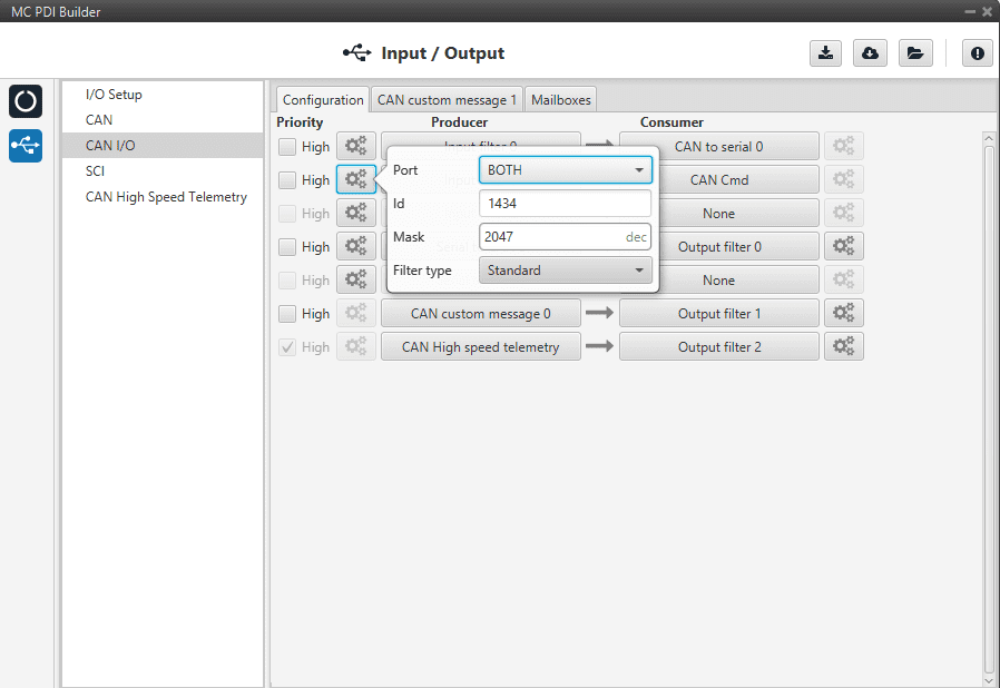
CAN I/O
This a common part that is shared with Veronte Autopilot products, please refer to CAN Setup section of 1x PDI Builder user manual for further information.
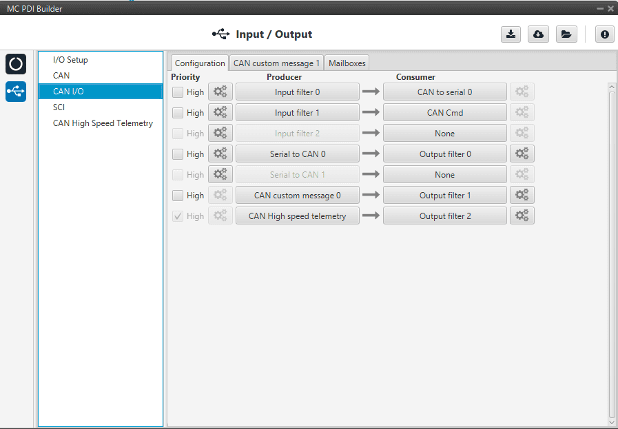
Altough, most of this menu could be familiar to veronte users, there is one new feature : CAN CMD. This is the input ESC expects to command the motor. By default, it uses the ID 1434 (standard) and the message structure is the following:
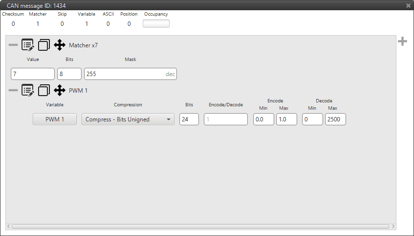
Warning
Note that what is represented as PWM1 is in fact sent as a value between 0 and 2500 as a result of the decoding factor. This last 24 bit value is in fact an RPM value.
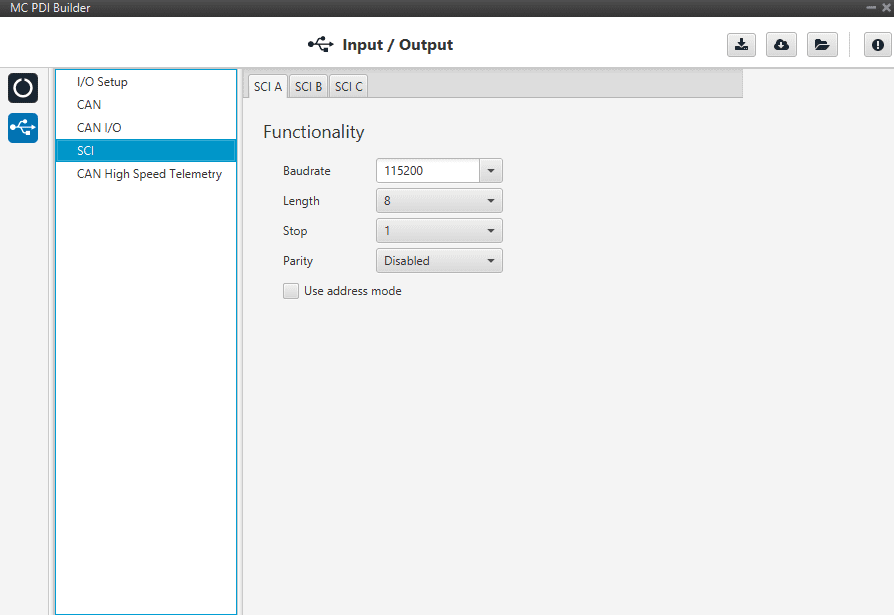
SCI
The following fields can be configured:
Baud rate: this field specifies how fast data is sent over a serial line.
Length: this field defines the number of data bits in each character.
Stop: stop bits sent at the end of every character.
Parity: is a method of detecting errors in transmission. When parity is used with a serial port, an extra data bit is sent with each data character, arranged so that the number of 1 bits in each character, including the parity bit, is always odd or always even.
CAN High Speed Telemetry
MC is equipped with an special CAN telemetry, which is faster than the regular one. This is meant to monitor all variables that are RPM dependent and can be crucial to tune your ESC during initial stages. For instance, seeing electrical angle can be extremely difficult with a low samplig rate at high RPMs and as a consequence, tuning the observer gain can be tough. Likewise, monitoring the current that is measured in each phase can represent the same issue and make PI tuning really time-consuming.
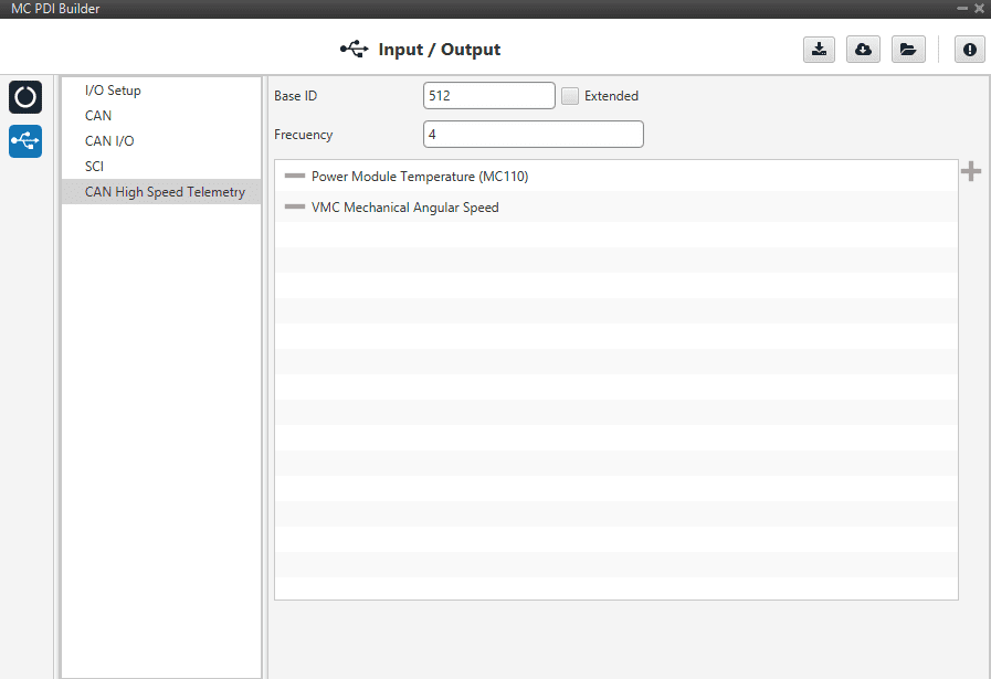
There are only two parameters here:
Base ID: the first ID to be used. The next IDs will be reserved depending on the variable list.
Frequency(decimation): the number of clock steps the ESC skips before sending a High Speed CAN telemetry packet.
Note
MC control is running at 5kHz.
Note
A separate tool is offered to see MC telemetry, please ask support@embention.com