Integration examples
CAN Isolator
CEX can operate as a CAN bus isolator, since it manages both CAN buses as desired. The system has a built-in microcontroller; which manages CAN buses in real-time. Both buses are not electrically connected, in consequence, electrical signals that do not follow the CAN protocol will be isolated.
The functionalities of a CAN isolator are the following:
The following diagram summarizes the behavior of CEX as a CAN bus isolator:
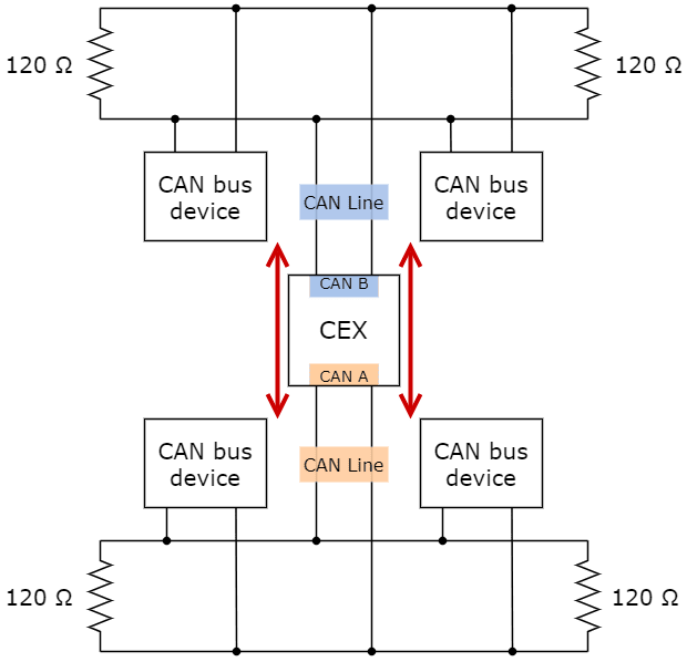
Subnets CAN diagram
Filtered CAN subnet
With CEX it is possible to isolate CAN nets by filtering certain messages from one CAN line and only transmitting specific information through CEX to the other one.
In this example, only a certain range of CAN IDs will be allowed to cross from one CAN line to the other using the two CAN ports of CEX. Specifically, information will pass from CAN B of CEX to CAN A of CEX.
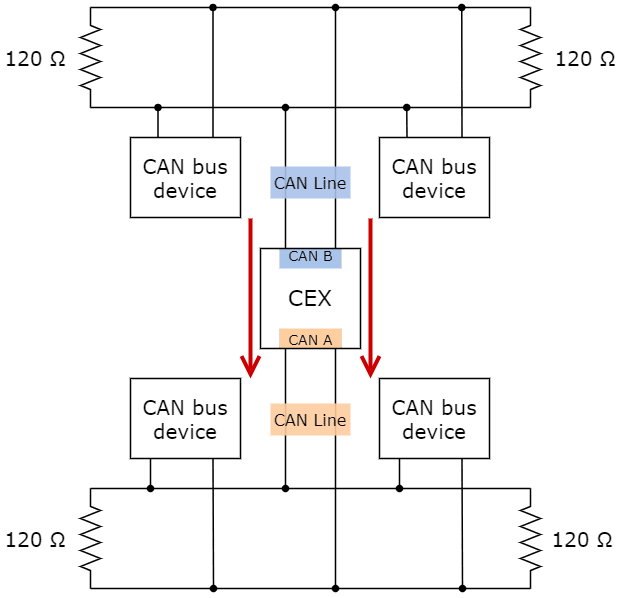
Subnets CAN example - From CAN B to CAN A
The allowed range will be from 0x550 to 0x55F.
Create a new mailbox entry for CAN B.
To do this, go to Input/Output menu \(\rightarrow\) CAN Setup panel \(\rightarrow\) CAN B tab.
Assign some of the mailboxes to it and set the ID to 0x550. This example uses an ID expressed in hexadecimal notation.

Filtered CAN subnet - Mailbox configuration
Set a Mask which will ignore the last 4 bits.
Note
Although the ID has been entered in hexadecimal notation, note that the Mask has been set in binary format.

Filtered CAN subnet - Mailbox mask configuration
Go to Input/Output menu \(\rightarrow\) CAN I/O panel \(\rightarrow\) Configuration tab.
Configure CAN Input Filter 2 on CAN B, with the same settings as the Mailbox.
Important
This menu only allows decimal numbers. For this example the Id 0x550, is represented as 1360 in decimal format, and the Mask is also represented in decimal format as 2032.

Filtered CAN subnet - CAN Input Filter configuration
Bind CAN Output Filter 2 to CAN Input Filter 2 and, configure the CAN Output Filter to CAN A.

Filtered CAN subnet - CAN Output Filter configuration
CAN tunnel
CAN tunnel is a specific type of message forwarding; where messages are tunneled from one CAN port of CEX to the other.
In this example, a transparent tunnel will be created. So, any messages received on Interface A will be sent through Interface B:
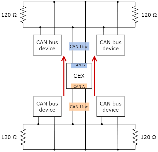
Subnets CAN example - From CAN A to CAN B
Optionally, the mailboxes can be equally distributed to support both standard and extended CAN IDs.
Create a new mailbox entry for Interface A.
To do this, go to Input/Output menu \(\rightarrow\) CAN Setup panel \(\rightarrow\) CAN A tab.
Assign half of the mailboxes to it and set a Mask of 0.

CAN tunnel - Mailbox configuration
Go to Input/Output menu \(\rightarrow\) CAN I/O panel \(\rightarrow\) Configuration tab.
Configure CAN Input Filter 2 on CAN A, with CAN id 0, a Mask of 0 and Both as frame format type.

CAN tunnel - CAN Input Filter configuration
Bind CAN Output Filter 2 to CAN Input Filter 2 and, configure the CAN Output Filter to CAN B.

CAN tunnel - CAN Output Filter configuration
Reading Arbitration Messages
Note that those messages are generated only if arbitration and the messages are enabled in CEX.
Arbiter will send its telemetry in little endian format, using its CAN-TX ID.
The appropriate arbitration message format is described in CAN Bus protocol -> Arbitration section of the CEX Software Manual.
External devices
The step-by-step instructions for the following external devices are explained in detail in the following sections: